28
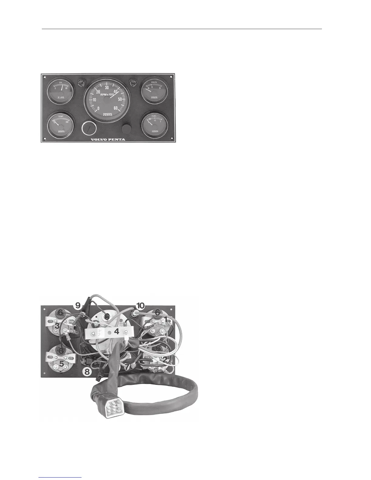
Wiring Diagram AQ171, 251DOHC
With Instrument panel alternative 1
1 . Oil pressure gauge
2. Temp gauge
3. Voltmeter
4. Tachometer
5. Fuel gauge (alternative)
6. Instrument lights
7. Key switch (B = 30, S = 50, I = 15)
8. Switch, instrument lights
9. Fuse 8 Amp
10. Fuse 8 Amp
11. Alternator
12. Starter motor
13. Terminal block
14. Automatic fuse 40 Amp
15. Main switch (optional)
16. Battery (optional)
17. Temp sender
18. Oil pressure sender
19. Distributor
20. Electronic ignition unit
21. Relay
22. Resistor
23. Impulse sender, ignition unit
24. Ground (screw)
25. Solenoid valve
Cable cross sections
AWG mm
2
16 1.5
13 2.5
10 6.0
8 10.0
Cable colour code
SB = Black
PU = Purple
LBN = Light brown
R = Red
GR = Grey
LBL = Light blue
R/Y = Red/Yellow
BN = Brown
W = White
Y = Yellow
13
 Loading...