49
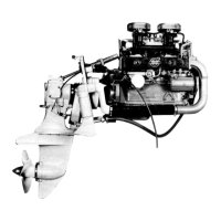
78. Insert the rubber mat in the heat exchanger
housing.
79. Put new seal rings on the cooling element.
Lubricate the seal rings with oil to facilitate the
installation of the element in the housing.
80. Center the cooling element carefully in the heat
exchanger housing and push it home. Make sure that
the rubber mat is properly clamped into its position.
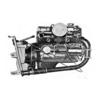
81. Put the pressure pad, the hard rubber pad and
the rubber gasket on the heat exchanger housing.
82. Install the cover and tighten the screws in a
criss-cross pattern, a little at the time.
NOTE! The cover will be pressed down approx-
imately 5 mm (0.25"). Allen key: 4 mm.
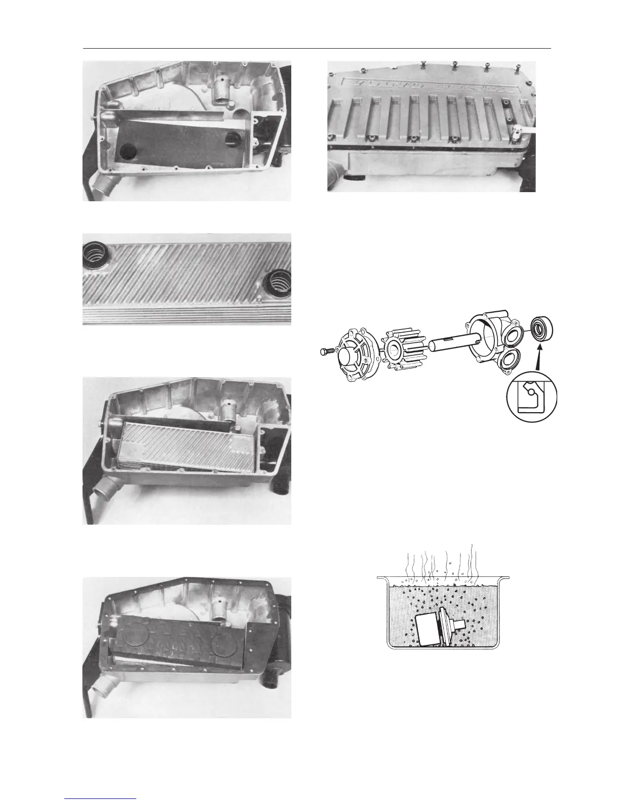
The sea water pump
83. Remove the cover on the sea water pump and
use pliers to pull out the impeller. Take care of the
key. Push out the seal ring. Install a new seal ring.
Turn the seal lip facing the impeller. Grease the seal
ring abundantly and carefully push the shaft into the
seal ring. Insert the key and install a new impeller.
Install the cover with a new gasket.
The thermostat
84. When necessary check the opening temperature
of the thermostat by lowering it into warm water. It
should begin opening at a temperature of 82°C
(180°F). Can be fully open at 92°C (198°F). Check
to make sure that the rubber seal is in good condi-
tion.
 Loading...