74
4G Installing the external
components of the Cylinder Head
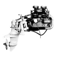
196. Install the timing gear cover. Tool width: Allen-
head 6 mm and hexagonal 10 mm.
197. Install the sea water pump. Tool width: 10 mm.
Make sure that the pump shaft engages the cross-
piece carrier.
198. Install the cooling water pipes on the sea water
pump. Check the seal. Replace if necessary.
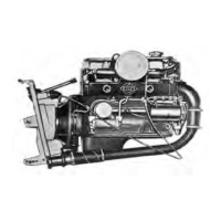
199. Install the V-belt and tension it to allow it to be
depressed approx. 5 mm (0.2") by normal thumb
pressure. Tool width: 1/2" and 16 mm.
NOTE! Make sure the V-belt enters the correct
groove on the crankshaft pulley.
200. Install the thermostat along with a new gasket
in the thermostat housing. Then install the thermo-
stat housing on the engine. Tool width: 10 mm.
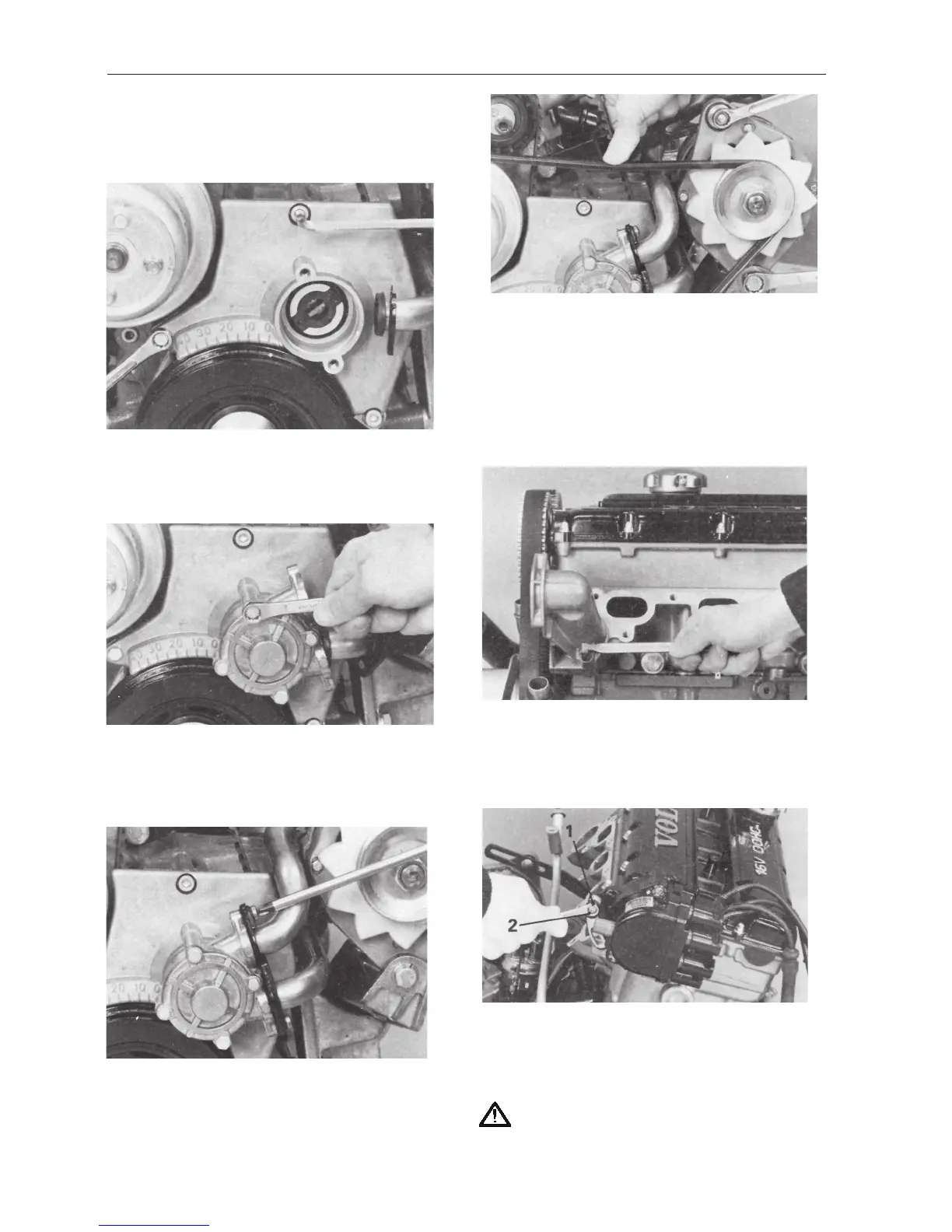
201. 251DOHC, AQ171. Make sure that the O-rings
on the distributor are not damaged. Replace if ne-
cessary. Grease the distributor shaft and install the
distributor on the engine. Tool width: 10 mm.
IMPORTANT: In order to position the distrib-
utor correctly, the plastic bushing (1) must be
installed with the screw (2).
 Loading...