Group
21
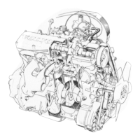
Reconditioning engine
Cylinder head, reconditioning
E5
Check camshaft end float
Position the camshaft and make sure that it turns
easi-
ly-
Fit the locking fork. Measure the end float with a feeler
gauge.
The clearance must not exceed max. 0.5 mm
(0.020 in). Replace the locking fork if the end float is too
large.
Remove the locking fork and camshaft.
E6
Check valve guide - valve clearances
Use a dial indicator.
Use new valves and press up 5-10 mm (0.2-0.4 in) with
finger when measuring.
The clearance must not exceed max. 0.15 mm (0.0059
in).
E7
Check valve springs
The springs are colour coded, and two different types
are used depending on engine type.
Colour
code
GREY
GREEN
Lenth,
Load
mm (in) N (lbs.)
47.2(1.86) 0 0
40.0(1.57)
233-268(52-60)
32.2(1.27)
521-585(116-131)
47.1 (1.85) 0 0
40.0(1.57) 230-266(51-59)
30.0(1.18) 613-689(137-154)
Valve guide replacement
Operatons
E8-14
E8
Press out valve guides
Use drift 5218.
Place the cylinder head on a sloping surface so that the
valve guides are vertical.
47