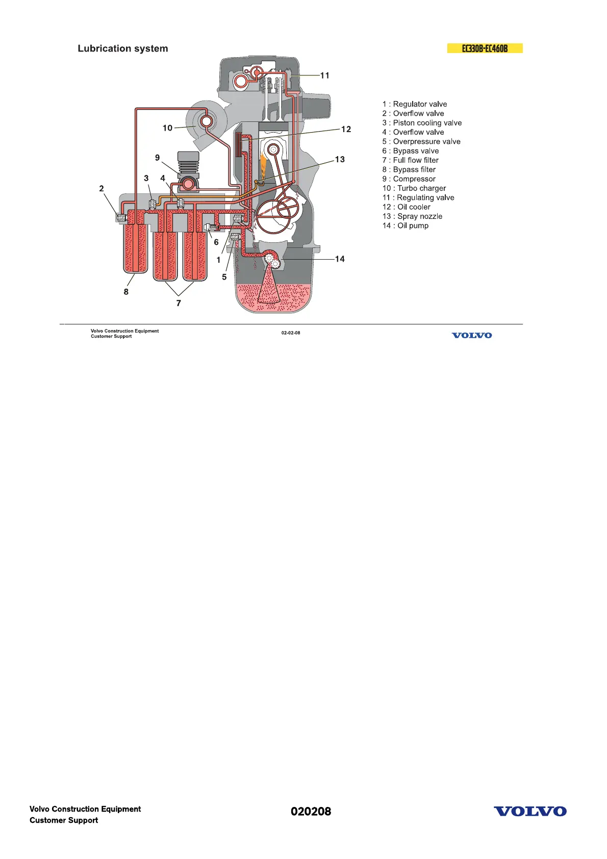
Lubrication system schematic
This is a schematic description of the lubricating system.
When the engine starts the gear driven pump forces the lubricating oil in to the filter housing. At low oil
temperature, for example when cold starting in the winter the bypass valve for the oil cooler will open so
the oil will reach the engine faster. From the full flow filters the oil is distributed to the bypass filter and
the engine block gallery then to all the engine lubricating points.
The turbo charger is lubricated with oil directly from the bypass filter.
The air compressor is lubricated via an external hose from the filter housing.
Oil return from the cylinder head
There are three oil return holes drilled through the cylinder head and block.
Oil pressure reducing
The regulator valve regulates the engine oil pressure and excess oil is led back to the sump.
Piston cooling
The valve for piston cooling is pressure sensitive and opens just above the normal idling pressure. The oil
is led in to the lengthways channel in the block and sprayed via nozzle, one for each piston, onto the
inside of the piston.
By-pass filter Overflow
The overflow valve for the bypass filter opens if the filter becomes blocked to ensure turbo lubrication.
Full flow filter Overflow
The overflow valve for the full flow filter opens if the filter becomes blocked to ensure engine
lubrication. Oil cooler bypass
When the engine starts and the oil temperature is low (low viscosity), the oil cooling bypass valve opens.
This is to lubricate the engine faster during cold start. When the oil temperature is stabilized (viscosity)
the valve closes and the oil passes through the oil cooler.