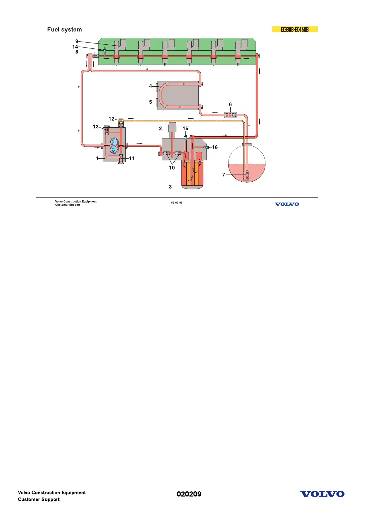
Fuel system principle
The fuel flow and valve function is schematically described. Light red means suction and dark red means
feed pressure.
The fuel is sucked up by the feeder pump (1) through the strainer (7) in the tank fitting, past the non-
return valve (6).The non-return valve opens and the fuel flows to the control unit and goes through the
cooling loop (5) ( if the control unit (4) has cooling ) up to the overflow valve (8) and from there, together
with the return fuel which passes through the overflow valve to the feeder pump suction side.
The feeder pump (1) forces the fuel to the filter housing, past both of the non-return valves (10) for the
hand pump (2) and at the same time valve (12) opens for the return fuel to the tank. If there is some air
in the system it will automatically be bleeded.
After through the filter (3), to the cylinder head lengthways channel to feed the injectors (9).
The overflow valve (8) maintains a constant pressure for the fuel feed to the injectors (9) and opens at the
pressure of 3,5 to 4,5 bar.
The pressure regulating valve (11) in the pump opens to reduce the pressure in the pump for example
during engine braking when the fuel injection is cut off.
Picture text: