Group 28 Troubleshooting
MID 128 SID 20 Timing Sleeve,
Check
Special tools: J-43233, J-39200, J-41132, J-
38748
D7C only
NOTE!
Check all the particular connectors for loose connections
as well as for switch resistance and oxidation.
For detailed circuit information, refer to:
Service
Manuals
Function Group 37
Electrical Schematics, VNL, VNM
IMPACT Function Group 2841
Information Type: Diagnostic “Fault
Codes”
Note that small resistances are difficult to measure. Use
the value instead as a standard value for an open in the
timing sleeve circuit.
Measurement at the component’s
connector, to the EECU
1
Note: An incorrect value (below) can
also cause the component to fail;
therefore, it is important to check the
component if any of the values are in-
correct.
2
Disconnect the connector to the timing
sleeve (7–pin connector on the rear of
the injection pump). Take measure-
ments on the wiring harness
connector only.
Ground wire:
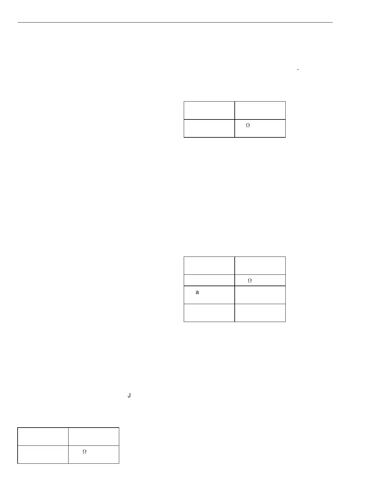
3
Measure the resistance with ohmme-
ter J-39200.
Ignition key must be in the OFF posi-
tion.
Measuring
points
Optimal value
4 / alternate
ground
60 k
J-39200
Supply wire:
4
Measure the resistance with ohmme-
ter J-39200.
Ignition key must be in the OFF posi-
tion.
Measuring
points
Optimal value
3 / alternate
ground
40
J-39200
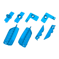
Check of component
Timing sleeve
1
Disconnect the connector to the timing
sleeve (7–pin connector on the rear of
the injection pump). Install breakout
box J-38748 to the pump connector
end only.
Measure the resistance with ohmme-
ter J-39200.
Ignition key must be in the OFF posi-
tion.
Measuring
points
Optimal value
3/4 1.3
3 / alternate
ground
open circuit
4 / alternate
ground
open circuit
J-38748
J-39200
164