Do you have a question about the Von Duprin WS9857-F and is the answer not in the manual?
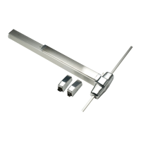
Ensures UL Tornado/Windstorm certification by using provided hardware.
Instructions for using the dogging key to lock down the pushbar.
Requirements for electric hinges and wiring for power transfer.
Marking the exit device centerline and aligning the strike.
Preparing holes for the strike and marking the door using templates.
Marking door locations for top and bottom latches using templates.
Drilling pilot holes as indicated by templates for secure mounting.
Marking and drilling holes for the top strike using the soffit as a template.
Securing the center case to the door using screws or sex bolts.
Guidance on cutting the device if necessary for installation.
Installing support screws and the center case cover.
Adjusting and securing the strike plate for proper latch engagement.
Applying grout to secure the strike in the floor.
Placing the top rod and ensuring the top latch clicks and holds securely.
Installing the guide for the top rod for proper operation.
Confirming top latch engagement and adjusting the strike if needed.
Installing the bottom rod fitting and sliding ends into respective slots.
Adjusting the bottom rod until the door opens and the latch clears the strike and floor.
Installing the guide for the bottom rod.
Testing the exit device operation for smooth latch engagement and retraction.
Installing the outer covers for the exit device.
| Product Type | Exit Device |
|---|---|
| Fire Rated | Yes |
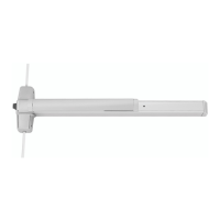
| Model | WS9857-F |
| Operation | Pushpad |
| Material | Steel |
| Finish | US32D |
| Door Width | Up to 48 inches |
| Door Thickness | 1-3/4 inches |
| Mounting | Surface Mount |
| Compliance | ANSI A156.3 |