Montage handleiding/Assembly manual/Montage-Anleitung/Manuel du montage 10/47
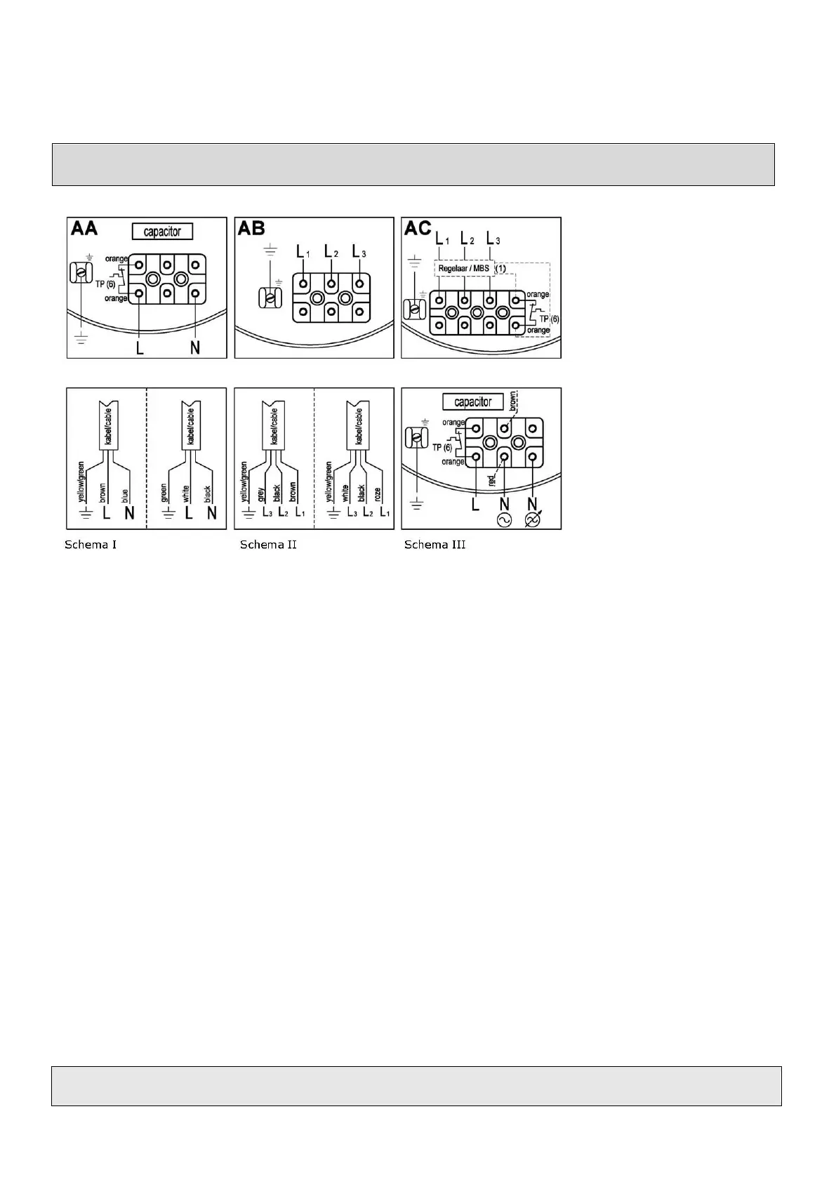
FIG.VII
Aansluitschema /Connection diagram / Anschlussdiagram /
Yellow/green: groen/geel;
Grün/gelb; Vert/jaune
Brown: Bruin; Braun; Brun
Blue: Blauw; Blau; Bleu
White: Wit; Weiß; Blanc
Black: Zwart; Schwarz; noir
Grey: Grijs; Grau; Gris
Roze: Roze; Rosa; Rose
Kabel/Cable: Kable/Câble
(6)
TP: Thermal Protection = Thermische beveiliging:
- Bij 1 fase: 250V 2,5A cosφ =1
- Bij 3 fase: 250V 10A cosφ =1
(6)
TP: Thermal Protection = Thermoschutz:
- Bei 1 Phase: 250V 2,5A cosφ =1
- Bei 3 Phase: 250V 10A cosφ =1
(6)
TP: Thermal Protection:
- At 1 phase: 250V 2,5A cosφ =1
- At 3 phase: 250V 10A cosφ =1
(6)
TP: Thermal Protection = Protection thermique
- A 1 phase : 250V 2,5A cosφ =1
- A 3 phase: 250V 10A cosφ =1