Installation and Operating Manual
LCD Solar Computer S No. 1250
Precise display of all important values, adapted to VOTRONIC SR- and
MPP-solar controllers 12 V and 24 V.
The following values are displayed:
- Charging current (A)
- Solar battery voltage (V)
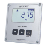
- Solar power (W)
- Solar current meter (Ah and Wh)
The LCD Solar Computer S has been particularly designed for operation in
connection with all VOTRONIC solar controllers since serial number 13V01.0000. A
large display with time-controlled illumination ensures excellent legibility. The solar charging current, the solar power and
the voltage of the solar battery are displayed. The instantaneous capacity of the solar modules is constantly displayed as
bar graph in steps of 10 % at the margin of the display.
The current meter function counts the "yielded" ampere hours and watt hours, thus simplifying the control of the solar
system. The counter values can be reset to zero at any time and at discretion.
The dimensions of the unit are perfectly adapted to the VOTRONIC modular system. The VOTRONIC modular system
includes the tank display units (fresh and sewage water, as well as feces), the LCD series (battery computer, voltmeter and
thermometer), as well as the switch and fuse panels.
Please read the mounting instructions and operating manual including the safety regulations
completely prior to starting connection and start-up.
The included control cable is specifically designed and tested for this application. It has to be used
necessarily for a proper function of the device. Using a seemingly similar cable can cause malfunction,
which is not covered by guaranty.
Installation and Connection
The small mounting depth (approx. 27 mm) of the electronic system allows flush mounting into furniture boards to ensure,
that an optimum installation place can always be chosen. The clear opening of the cutout is min. 71 x 66 mm to ensure safe
alignment of the front panel. Please use the delivered drilling jig, which has been designed to consider combination with
further display panels.
If possible, the rear cutout opening should be covered with electrically nonconducting material to ensure efficient
protection of the electronic system and full utilization of the storage space, which might be located behind.
The delivered control cable of 5 m length is used to connect the display unit to the VOTRONIC Solar Controller (connection
"Solar Display"). The connection is executed ready to be plugged in, and the cable should be laid according to the safety
instructions.
Now the unit is ready for operation.
If the length of the control cable is not sufficient for connection of the connection unit, the cable extension of 5 m length,
order No. 2005, being available as accessory can be used. The total cable length is then 10 m.
Initial Start-up:
Connect the solar controller according to the instructions to be ready for operation, and make the plug-type connection
between display and VOTRONIC Solar Controller. Now, also the Solar Computer is ready for operation.