EasyManua.ls Logo

Votronic Switch Unit 100 User Manual

Votronic Switch Unit 100
4 pages
To Next Page IconTo Next Page
Page #1 background imageLoading...
Page #1 background image
Installation and Operating Manual
Switch Unit 100 Switching Capacity 12V or 24 V / 100 A No. 2072
VOTRONIC Switch Unit 100 works on basis of a bistable relay allowing very high capacities combined with a very low
own consumption. It suits especially as a remote-controlled main switch or load relay which is on long-term power. The
current carrying capacity conducts 100 A.
Switch Unit 100 can be mote-controlled by a normal switch (1 pol. ON / OFF).
Furthermore the consumer can be switched on and off through an emergency switch at the relay by hand.
The ranges of application are campers, intervention vehicles and boats:
Easy selection through ON / OFF switch
High switching current 100 A, short time to 150 A loadable
Applicable as battery main switch through ON / OFF switch (remote-controlled)
Switching state monitor is visible from the outside
Electronical delay prevent fast reactions like voltage drop or using strong consumer
Suitable for long-term usage due to a very low consumption of the Switch Unit (compliant EN13976)
No own electricity consumption if switched off with an external switch (remote-control)
Automatical disconnection by under voltage 8.5 V (minimum operating voltage of Switch Unit 100)
Switch Unit 100 cannot be used as a safety relay (emergency switch) to switch off dangerous
machines or engines. Please check safety regulations!
Please read this operating and installation manual thoroughly prior to connection and
start-up.
Installation:
1. Chose an installation place being cleaned and being protected from humidity and dust.
2. The installation place of the unit should be chosen in such a way, that the cables of battery and consumers can
be as short as possible (losses) and that the pushbutton "EMERGENCY" is easily accessible. The unit should
never be covered by any objects.
3. The switch unit is fastened solidly with screws in the casing flanges. The unit can be installed in any position.
But please make sure that the connection terminals are easy to reach
4. Observe to fasten the connection cables in such a way, that neither high tensible force, nor high force of
pressure is acting on the terminals.
Connection: (Please regard the connection plan)
ALWAYS DISCONNECT THE POWER SUPPLY TO THE BATTERY PRIOR TO WORKING ON THE
ELECTRIC SYSTEM TO AVOID SHORT-CIRCUITS!
It is recommendable to use connection cables of different colours to avoid malfunctions due to mixed up connections.
Observe: Only use red cables for plus "+" connection and black cables for minus "-" connection.
The 2pol. screw terminal is connected correctly when cable lengths show to the right and the crews show up. The unit
will not be damaged by eventual wrong polarization, but it will not be operating. Imperatively observe the cable cross
sections and the polarity. Insert the fuses near the battery (safety for cable fire).
Question and Answer IconNeed help?

Do you have a question about the Votronic Switch Unit 100 and is the answer not in the manual?

Votronic Switch Unit 100 Specifications

General IconGeneral
BrandVotronic
ModelSwitch Unit 100
CategorySwitch
LanguageEnglish

Summary

Switch Unit 100 Product Overview

Installation Guide

Provides instructions for selecting a clean, protected installation location and securing the unit.

Connection Instructions

Details on disconnecting power, using correct cable colors, and ensuring secure terminal connections.

Start-up and Operation

Switching the Unit ON

Methods for activating the Switch Unit via external switch or manual lever.

Switching the Unit OFF

Procedures for deactivating the unit using external controls or automatic undervoltage.

Application Example: Remote Main Switch

Demonstrates using the Switch Unit as a remote-controlled main switch in a living area.

Safety Regulations and Usage

Appropriate Application Restrictions

Defines the intended use as a power relay and outlines where it should not be applied.

General Safety Precautions

Covers cable management, environmental protection, electrical work, and user supervision.

Warranty and Liability Information

Details the warranty period, conditions for voiding warranty, and liability exclusions.

Technical Specifications and Compliance

Key Technical Data

Summarizes operating voltage, current consumption, switching capacity, and temperature range.

Declaration of Conformity

Lists directives, standards, and normative documents the product complies with.

Delivery Scope Contents

Outlines the items included in the product package.
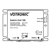
Related product manuals