VRG CONTROLS LLC. 8 of 60 JUNE 2021
VPC “BV” SERIES VALVE PILOT CONTROLLERS
INSTRUCTION MANUAL
VRG Controls LLC. 8 of 54 APRIL 21, 2019
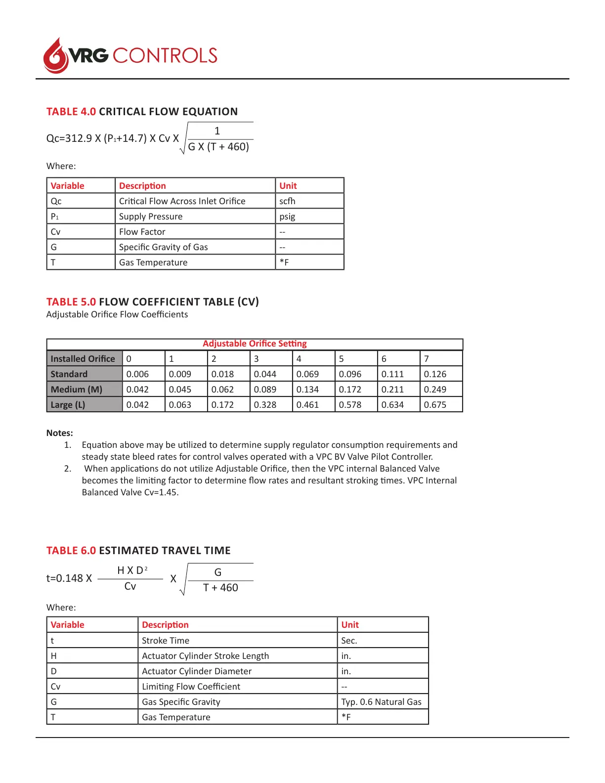
Variable Descripon Unit
Qc Crical Flow Across Inlet Orice sc
P1 Supply Pressure psig
Cv Flow Factor --
G Specic Gravity of Gas --
T Gas Temperature *F
TABLE 4.0 CRITICAL FLOW EQUATION
Qc=312.9 X (P
1+14.7) X Cv X
1
G X (T + 460)
Where:
TABLE 5.0 FLOW COEFFICIENT TABLE (CV)
Adjustable Orice Flow Coecients
Installed Orice 0 1 2 3 4 5 6 7
Standard 0.006 0.009 0.018 0.044 0.069 0.096 0.111 0.126
Medium (M) 0.042 0.045 0.062 0.089 0.134 0.172 0.211 0.249
Large (L) 0.042 0.063 0.172 0.328 0.461 0.578 0.634 0.675
Adjustable Orice Seng
Notes:
1. Equaon above may be ulized to determine supply regulator consumpon requirements and
steady state bleed rates for control valves operated with a VPC BV Valve Pilot Controller.
2. When applicaons do not ulize Adjustable Orice, then the VPC internal Balanced Valve
becomes the liming factor to determine ow rates and resultant stroking mes. VPC Internal
Balanced Valve Cv=1.45.
Variable Descripon Unit
t Stroke Time Sec.
H Actuator Cylinder Stroke Length in.
D Actuator Cylinder Diameter in.
Cv Liming Flow Coecient --
G Gas Specic Gravity Typ. 0.6 Natural Gas
T Gas Temperature *F
TABLE 6.0 ESTIMATED TRAVEL TIME
Where:
t=0.148 X
G
T + 460
H X D
Cv
2
X
 Loading...