VRG CONTROLS LLC. 9 of 60 JUNE 2021
VRG Controls LLC. 9 of 54 APRIL 21, 2019
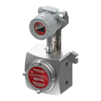
VPC “BV” SERIES VALVE PILOT CONTROLLERS
INSTRUCTION MANUAL
HOW IT WORKS DESCRIPTIONS:
DIRECT ACTING VPC-SA-BV
When the SENSING pressure is equal to the VPC setpoint, the net
force on the VPC power module is zero. This is the equilibrium
or “balanced” condion where the sensing pressure that pushes
down on the sensing diaphragm and the control spring force
that pulls up on the sensing diaphragm are equal. When the VPC
achieves equilibrium, the SUPPLY balanced valve and EXHAUST
balanced valve assemblies will remain closed maintaining a
constant OUTPUT pressure to the control valve. The VPC will
exhibit ZERO emissions at this state. From this posion two
possible scenarios can occur, the sensing pressure can rise above
or below the set point.
If the sensing pressure rises above the VPC setpoint the net force
on the VPC power module is downward. The EXHAUST balance
valve will close. The SUPPLY balance valve opens, increasing the
ow of SUPPLY gas to the OUTPUT port. The combinaon of these
acons creates a rise in output pressure. If the sensing pressure
falls below the VPC setpoint the net force on the VPC power
module is upward. Now the SUPPLY balanced valve will close.
The EXHAUST balanced valve opens, increasing the ow of gas to
the EXHAUST port. The combinaon of these acons decreases
the OUTPUT pressure. In order to control how much gas passes
through the balanced valve, adjustable orices are installed to
restrict the ow via the SUPPLY and the EXHAUST.
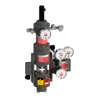
DIRECT ACTING VPC-SA-BV-ID
The VPC is inherently an INTEGRAL funcon device. A DERIVATIVE
funcon may be added to the OUTPUT of the VPC by incorporang
a VOLUME TANK in conjuncon with an adjustable orice on the
OUTPUT signal. The DERIVATIVE component aects the rate at
which the OUTPUT signal change is applied to the control valve
unit. If the DERIVATIVE orice number is increased this will cause a
slower resultant change in OUTPUT pressure (signal) to the control
valve. Conversely, if the DERIVATIVE orice number is decreased
it will permit a more rapid change in OUTPUT pressure (signal)
to the control valve unit. The DERIVATIVE funcon is typically
incorporated to introduce addional stability when the VPC is
applied in conjuncon with a pneumac valve posioner or when
the installed system is has a rapidly aected downstream system
such as a power plant fuel gas feed or two-stage pressure cut
applicaon.
REVERSE ACTING VPC-SA-BV-ID
In this case, the SUPPLY pressure and the EXHAUST pressure are
routed dierently by changing the ORIFICE manifolds. The VPC
will exhibit behavior in a “reverse” scenario. When SENSING
pressure rises above the set point the net force on the VPC power
module pushes downward. The SUPPLY balanced valve will close
and the EXHAUST balanced valve will open, causing gas to vent
through the EXHAUST port. This results in a decrease of OUTPUT
pressure. If the SENSING pressure falls below the VPC setpoint,
the net force on the VPC power module is upward. The SUPPLY
balanced valve will open and the EXHAUST balanced valve will
close causing an increase in OUTPUT pressure. Any VPC “Single
Any VPC “Single Acng” model maybe easily converted
between Direct Acng and Reverse Acng by simply
swapping the posion of the SUPPLY/EXHAUST and OUTPUT
manifolds.
VPC-SA-BV-GAP
For “How it Works” descripon of the VPC-SA-BV-GAP,
reference Direct Acng VPC-SA-BV at top of this page. The
VPC-SA-BV-GAP will dier in construcon by not having
ADJUSTABLE ORIFICES installed. The “GAP Controller”
will dier operaonally as it operates with a “snap acng”
or “on-o” logic. The “on-o” logic produces a HIGH
SETPOINT and LOW SETPOINT which area separated by a
“BAND.” This “BAND” or dierence between the two (2)
setpoints is achieved by widening the deadband via the
SETPOINT ADJUSTMENT DRUM.
DOUBLE ACTING VPC-DA-BV
When the SENSING pressure is equal to the VPC-DA-BV
setpoint, the net force on the VPC-DA-BV power module is
zero. This is the equilibrium or “balanced” condion where
the sensing pressure that pushes down on the sensing
diaphragm and the control spring force that pulls up on
the sensing diaphragm are equal. When the VPC-DA-BV
achieves equilibrium, the OPEN balanced valve and CLOSE
balanced valve assemblies will remain closed maintaining a
constant OUTPUT pressure to the top and boom chambers
of the control valve actuator.
From this posion two possible scenarios can occur, the
sensing pressure can rise above or below the set point.
If the sensing pressure rises above the VPC-DA-BV
setpoint the net force on the VPC-DA-BV power module is
downward. The OPEN balance valve will open and divert
pressure from the OPEN chamber of the double acng
actuator to EXHAUST. The CLOSE balance valve will remain
closed and full SUPPLY pressure shall connue to be applied
to the CLOSE side of the double acng actuator. The
combinaon of these acons creates a dierenal pressure
to be applied to the double acng actuator that will move
the valve toward the closed posion.
If the sensing pressure falls below the VPC-DA-BV setpoint
the net force on the VPC-DA-BV power module is upward.
The CLOSE balance valve will open and divert pressure
from the CLOSE chamber of the double acng actuator to
EXHAUST. The OPEN balance valve will remain closed and
full SUPPLY pressure shall connue to be applied to the
OPEN side of the double acng actuator. The combinaon
of these acons creates a dierenal pressure to be applied
to the double acng actuator that will move the valve
toward the open posion.
Addion of an NVD No-Vent Device will eliminate emissions
when the control valve remains in the full-open or full-
closed posions such as a standby, overpressure monitor or
relief type applicaon.
 Loading...