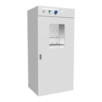
The VWR General Purpose Incubator, models 1915A-2 and 1925A-2, is a large capacity incubator designed for professional, industrial, or educational use where the preparation or testing of materials is done at an ambient air pressure range of 22.14 – 31.3 inHg (75 – 106 kPa) and no flammable, volatile, or combustible materials are being heated. These units are intended for use indoors, at room temperatures between 15°C and 30°C (59°F and 86°F), at no greater than 80% Relative Humidity (at 25°C / 77°F). Operating these units outside of these conditions may adversely affect its incubator temperature stability and effective operating range.
Function Description
The VWR General Purpose Incubator provides a controlled environment for various applications requiring precise temperature regulation. It functions by heating and maintaining a user-selected target set point within the chamber. A solid-state probe monitors the chamber's internal temperature, and a PID (Proportional-Integral-Derivative) control loop continuously adjusts heating rates to compensate for environmental changes and maintain the set temperature. Air circulation within the chamber ensures uniform temperature distribution. The incubator also features an Over Temperature Limit (OTL) system, which acts as a safety mechanism to prevent overheating by cutting off power to the heating elements if the chamber temperature exceeds a predefined limit. The units are equipped with internal power outlets for accessories like stirrers or shakers, allowing for enhanced functionality within the controlled environment.
Important Technical Specifications
Electrical:
- Voltage: 220 – 240 Volts
- Frequency: 50/60 Hz
- Amperage:
- 1915A-2: 8.0 Amps
- 1925A-2: 8.5 Amps
- Power Cord: 250 Volt, 10 Amp, 8.2 feet (2.5m), CEE7/7 standard wall socket.
- Circuit Breaker: 20 amps recommended wall circuit breaker.
- Internal Power Outlets: Four 220 – 240-volt, 1-amp power outlets inside the chamber. Do not attach powered equipment that draws more than 1 amp.
Dimensions (In Inches):
- 1915A-2:
- Exterior (W x D x H): 38.8 x 34.3 x 76.9 in
- Interior (W x D x H): 32.5 x 26.0 x 63.3 in
- 1925A-2:
- Exterior (W x D x H): 41.5 x 34.3 x 90.3 in
- Interior (W x D x H): 35.6 x 26.0 x 76.0 in
Dimensions (In Millimeters):
- 1915A-2:
- Exterior (W x D x H): 985 x 871 x 1953 mm
- Interior (W x D x H): 825 x 660 x 1607 mm
- 1925A-2:
- Exterior (W x D x H): 1054 x 872 x 2293 mm
- Interior (W x D x H): 904 x 660 x 1930 mm
Weight:
- 1915A-2:
- Shipping: 570 lb / 259 kg
- Net: 406.0 lb / 184.0 kg
- 1925A-2:
- Shipping: 657 lb / 298 kg
- Net: 497.0 lb / 225.0 kg
Chamber Volume:
- 1915A-2:
- Cubic Feet: 30.9
- Liters: 874.0
- 1925A-2:
- Cubic Feet: 38.6
- Liters: 1093.0
Shelf Capacity:
- Maximum Weight per Shelf: 75.0 lb / 34.0 kg
- Max Total Weight: 450.0 lb / 204.0 kg (for both models)
- Note: Weight distributed evenly across the shelf. Exceeding this weight limit risks damaging the shelf standard rails and the chamber liner.
- Shelves Included:
- 1915A-2: 6 shelves
- 1925A-2: 6 shelves
Temperature:
- Range: Ambient +8° to 70°C
- Uniformity: ±0.8°C @ 37°C
- Stability: ±0.1°C
Required Clearances:
- Sides: 2 inches (51 mm)
- Rear: 4 inches (102 mm)
- Top: 2 inches (51 mm) of headspace clearance is required between the top of the unit and any overhead partitions.
Deionized and Distilled Water Requirements:
- Use of deionized water may corrode metal surfaces and voids the manufacturing warranty.
- The manufacturer recommends the use of distilled water in the resistance range of 50K Ohm/cm to 1M Ohm/cm, or a conductivity range of 20.0 uS/cm to 1.0 uS/cm, for cleaning applications.
Usage Features
Installation:
- Pre-Installation Checklist: Verify required ambient conditions, spacing clearance, unit dimensions, and suitable electrical outlet and power supply.
- Incubator Installation: Review lifting and handling instructions, install leveling feet, and install the unit in its workspace location.
- Incubator Setup: Clean and disinfect the unit and shelving, install shelving, and verify the port cap is installed in the access port.
- Lifting and Handling: The unit is heavy; appropriate lifting devices are required. Lift the unit only from its bottom surface. Doors, handles, and knobs are not adequate for lifting or stabilization. Restrain the unit completely while lifting or transporting. Remove all moving parts, such as shelves and trays, and lock doors in the closed position during transfers to prevent shifting and damage.
- Leveling: Install the 4 leveling feet in the 4 corner holes on the bottom of the unit. The unit must be level and stable for safe operation. To prevent damage when moving the unit, turn all 4 leveling feet so that the leg of each foot sits inside the unit.
- Shelving Installation: Install 4 shelf clips on the sides of the shelf standard mounting rails. Squeeze each clip, insert the top tab first, then the bottom tab using a rocking motion. Place the shelf and verify it is level.
- Access Port: Always leave the access port cap in place, except when introducing sensor probes into the chamber. Removing the cap during normal operations can adversely impact temperature stability and uniformity.
Operation:
- Power On: Plug in the power cord and turn on the incubator using the ON (I) position switch.
- Setting Temperature Set Point:
- Press and hold the Up or Down arrow buttons simultaneously for approximately 5 seconds.
- Briefly push and release either the Up or Down arrow buttons to activate the temperature set point adjustment mode. The display will briefly flash the letters "SP", then show the flashing, adjustable temperature set point. The display will automatically exit the adjustment mode after 5 seconds of inactivity, with the last shown set point value saved.
- Use the Up and Down arrow buttons to change the temperature set point.
- Wait 5 seconds after entering the Set Point. The display will stop flashing, and the set point is now saved in the controller. The chamber will now automatically heat or passively cool to match your set point. The display will revert to showing the current chamber air temperature.
- Setting Over Temperature Limit (OTL):
- Set OTL control to its maximum setting, if not already set to max.
- Turn the dial counterclockwise (left) until the Over Temperature Activated light illuminates. There is a soft click when the OTL begins rerouting power away from the heating elements.
- Slowly turn the dial clockwise (right) until the Over Temperature light turns off. The Over Temperature Limit is now set approximately 1°C above the current chamber air temperature.
- Leave the OTL dial set just above the activation point.
- Optional: Turn the dial slightly to the left (counterclockwise). This sets the cutoff threshold nearer to the current chamber temperature.
- Note: The OTL system at least once per year to verify its functionality. Failure to set the OTL voids the manufacturing defect warranty if over temperature damage occurs.
- Loading Samples: The manufacturer strongly recommends waiting at least 8 hours after putting the incubator in operation before loading samples. Samples should be placed at least 1 inch (25 mm) away from the chamber walls. Proper spacing allows for maximum air circulation and a higher degree of temperature uniformity. Proper spacing also decreases the chance of condensate forming in the incubator when operating with a large number of samples.
- Humidifying the Incubator: Long-term use of a large water container, such as a humidifier pan, will create excess water vapor in the unit and can damage the electrical components of the incubator. Additionally, the use of deionized water may cause significant corrosion damage to the incubator. Overloading the unit with sample media may also damage the incubator from excessive media evaporation and disruption of air flow pathways through the shelf space.
- Small Sample Load: Placing a small number of Petri dishes or other media containers in the incubator chamber may lead to excessively fast drying of sample media. A small water-filled container, such as an open flask, may be placed in the chamber to help slow sample drying with small loads.
Maintenance Features
Cleaning and Disinfecting:
- Warning: Disconnect the unit from its power supply prior to performing maintenance or services.
- If a hazardous material or substance has spilled in the unit chamber, immediately initiate your site Hazardous Material Spill Containment protocol. Contact your local Site Safety Officer and follow instructions per the site policy and procedures.
- Periodic cleaning and disinfection are required.
- Do not use spray-on cleaners or disinfectants. These can leak through openings and coat electrical components.
- Consult with the manufacturer or their agent if you have any doubts about the compatibility of decontamination or cleaning agents with the parts of the equipment or with the material contained in it.
- Do not use cleaners or disinfectants that contain solvents capable of harming paint coatings or stainless steel surfaces. Do not use chlorine-based bleaches or abrasives; these will damage the chamber liner.
- Warning: Exercise caution if cleaning the unit with alcohol or flammable cleaners. Always allow the unit to cool down to room temperature prior to cleaning and make sure all cleaning agents have evaporated or otherwise been completely removed prior to putting the unit back into service.
- Cleaning Steps:
- Disconnect the unit from its power supply.
- Remove all removable interior components such as shelving and accessories.
- Clean the unit with a mild soap and water solution, including all corners.
- Do not use an abrasive cleaner. These will damage metal surfaces.
- Do not use deionized water to rinse or clean with.
- Take special care when cleaning around the temperature sensor probes in the chamber to prevent damage. Do not clean the probes.
- Rinse with distilled water and wipe dry with a soft cloth.
Disinfecting:
- Always turn off and disconnect the unit to safeguard against electrical hazards.
- For maximum effectiveness, disinfection procedures are typically performed after cleaning.
- Disinfect the unit chamber using commercially available disinfectants that are non-corrosive, non-abrasive, and suitable for use on stainless steel and glass surfaces. Contact your local Site Safety Officer for detailed information on which disinfectants are compatible with your applications.
- If permitted by your protocol, remove all removable interior accessories (shelving and other non-attached items) from the chamber.
- Disinfect all surfaces in the chamber, making sure to thoroughly disinfect the corners. Exercise care to avoid damaging the sensor probes.
- Gas concentrations from evaporating disinfecting agents can inhibit growth or cause metabolic symptoms in microbiological sample populations. Make sure that chlorines, quaternary ammonias, or any other overtly volatile disinfecting agents have been rinsed or otherwise removed from the chamber surfaces, prior to placing samples in the chamber.
- When disinfecting external surfaces, use disinfectants that will not damage painted metal, glass, and plastic.
Minimizing Contamination Exposure:
- Suggestions for minimizing exposure of the incubator chamber to potential contaminants:
- Maintain a high air quality in the laboratory workspaces around the incubator.
- Avoid placing the incubator near sources of air movement such as doors, air vents, or high traffic routes in the workspace.
- Minimize the number of times the incubator chamber door is opened during normal operations.
Door Components:
- Periodically, inspect the door latch, trim, catch, and gasket for signs of deterioration. Failure to maintain the integrity of the door system shortens the life span of the unit.
Electrical Components:
- Electrical components do not require maintenance. If the incubator fails to operate as specified, please contact your distributor or Technical Support for assistance.
Storing the Incubator:
- Perform the following steps if the incubator will be out of use for more than 24 hours to prevent microbiological contamination such as fungus or mold:
- Depower the incubator.
- Disinfect and clean if required by your laboratory protocol, or if the chamber has been exposed to pathogenic microorganisms.
- Use a soft cloth to dry the chamber surfaces.
Calibrate the Temperature Display:
- Note: Performing a temperature display calibration requires a temperature reference device. Please see the Reference Sensor Device entry on page 7 for the device requirements.
- Temperature calibrations are performed to match an incubator temperature display to the actual air temperature inside the incubation chamber. The actual air temperature is supplied by a calibrated reference device. Calibrations compensate for long-term drifts in the incubator microprocessor controller as well as those caused by the natural material evolution of the sensor probe in the heated incubator space. Calibrations often are required by your laboratory or production protocol, or regulatory compliance schedule. Always calibrate to the standards and use the calibration setup required by your industry requirements or laboratory protocol.
- Suggested Calibration Setup:
- Introduce the reference device thermocouple probe through the access port on the left side of the unit.
- Position the sensor probe head as close as possible to the geometric center point of the chamber. The probe head must be at least 2 inches (51 mm) above or below shelving surfaces to prevent heat sinking. Secure the probe head in position using the non-stick tape.
- After securing the probe head in position, carefully place the access port cap in the port over the probe wires. Use non-stick tape to seal any gaps created between the cap and the port by the probe wires.
- The incubator door must be closed and latched. Failure to do so will prevent an accurate calibration.
- Temperature Calibration Procedure:
- Once the unit temperature has stabilized, compare the reference device and incubator temperature display readings.
- If the readings are the same, or the difference between the two falls within the acceptable range of your protocol, the display is accurately showing the temperature in the chamber. The Temperature Calibration procedure is now complete.
- If the difference falls outside of your protocol range, advance to step 2.
- A display calibration adjustment must be entered to match the display to the reference device. See the next step.
- Place the display in temperature calibration mode.
- Press and hold both the Up and Down temperature arrow buttons simultaneously for approximately 5 seconds.
- Release the buttons when the temperature display shows the letters "C O". The display will begin flashing the current temperature display value.
- Note: The display will automatically exit calibration mode after 5 seconds of inactivity, with the last shown temperature display value saved.
- Use the Up and Down arrow buttons to adjust the current display temperature value until it matches the reference device temperature reading.
- After matching the display to the reference device, wait 5 seconds.
- The temperature display will cease flashing and store the corrected chamber display value.
- The incubator will now begin heating or passively cooling in order to reach the set point with the corrected display value.
- Allow the incubator to operate for at least 1 hour undisturbed to stabilize after the incubator has achieved the corrected temperature set point.
- Failure to wait until the incubator is fully stabilized will result in an inaccurate reading.
- Compare the reference device reading with the chamber temperature display.
- If the reference device and the chamber temperature display readings are the same or the difference falls within the range of your protocol, the incubator is now calibrated for temperature.
- See the next step if the readings fail to match or fall outside of your protocol range.
- If the difference still falls outside the acceptable range of your protocol, repeat steps 3 – 7 up to two more times.
- If the temperature readings of the incubator temperature display and the reference device still fall outside your protocol after 3 calibration attempts, contact your distributor or technical support for assistance.