Page 4
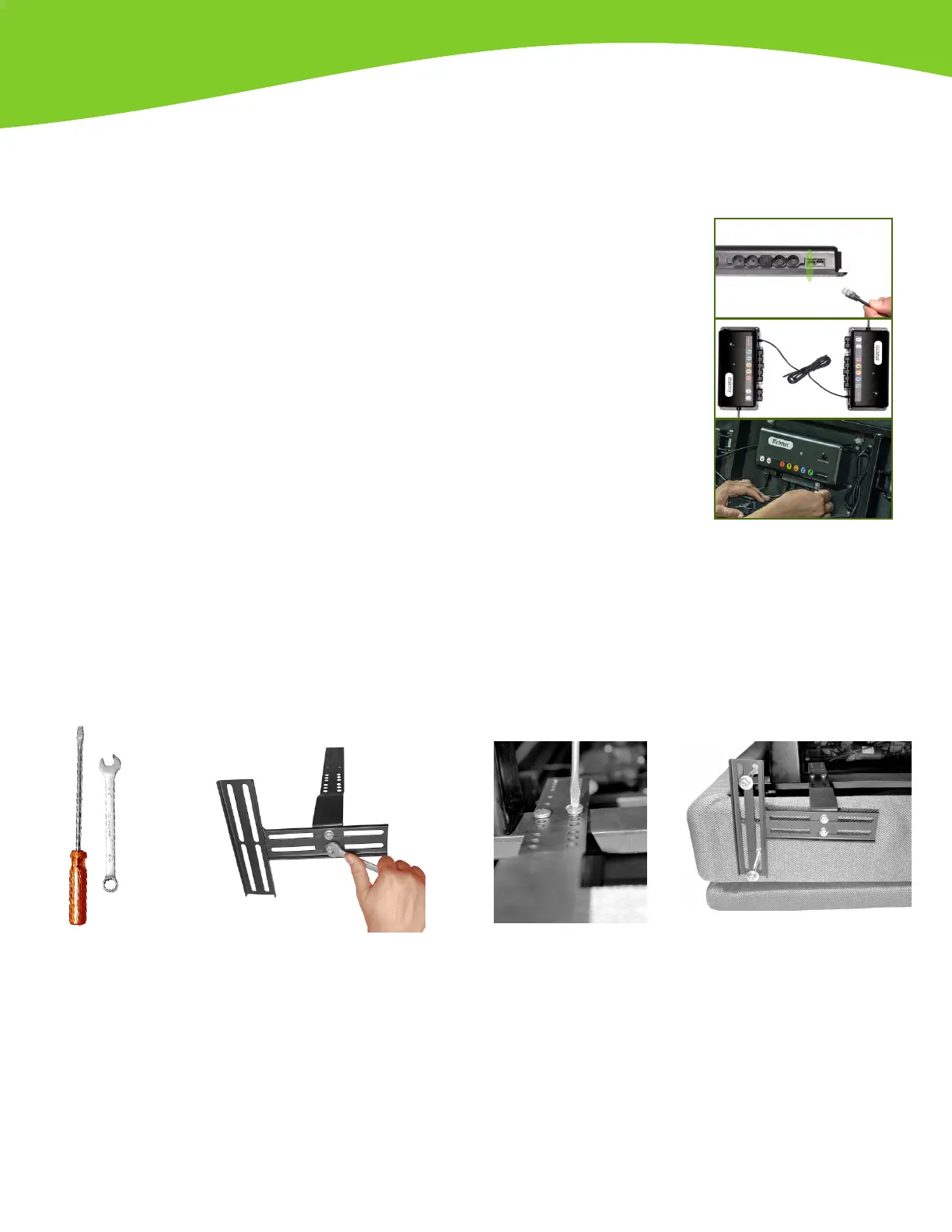
1) Attach one pair of brackets with
screws, washers and nuts provided.
Leave them loose enough to allow
outer bracket to slide (these nuts
need to be tightened on step 3).
Repeat with the second pair of
brackets with the outer bracket
facing the opposite side. Base unit
needs to be on a at surface with
the top side facing down before
continuing with step 2.
2) Join the bracket to the bed frame
as you need it. Select a hole that will
leave a space between 1.5” (38 mm)
and 2” (51 mm) between the edge
of the base and headboard brackets.
Continue with next steps of base
assembly before proceeding to
next step of attaching headboard
legs.
3) After nishing the base
assembly, you can attach the
legs of the headboard to the
headboard brackets using the
nuts, washers and bolts that
are provided. After rmly
attaching legs of headboard,
tighten the bolts and nuts
that attach the two brackets
together.
Step 8 - Optional
If your bed has a headboard, and you purchased the optional Headboard Bracket kit to attach the base to your
headboard follow these instructions for assembly. If you do not require a headboard bracket, then you can skip
this step.
Note: Optional headboard bracket kits are sold separately.
Tools
needed
When using your
own headboard:
Plain screwdriver
and a 7/16” or
adjustable wrench.
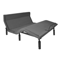
Step 7 - Two Base Synchronization (Split Sizes Only) - Optional
Use if you are setting up two Twin XL bases to use with one King size mattress, or when setting up two parts of Split California King base
model with one Cal-King mattress.
Using one King or Cal-King mattress with two Twin XL or Cal-King bases requires
synchronization of both control boxes, this function allows remote controls to operate
both units together. This is achieved by connecting the “Sync Cable” to each of the
control boxes. Locate the sync cable in the accessories box and control boxes
attached underneath the bases (see “Parts List” section). Plug one side of the sync
cable into the “Sync Cable” inlet of rst control box, repeat procedure with the
other side of the sync cable on the second control box.
NOTE: You might receive two sync cables (one with each base), make sure to
use and connect only ONE sync cable. Please make sure identify sync cable inlet
port correctly, which is labeled as “SYNC”. Control box might have a similar port
labeled as “APP” (bluetooth module port). Connecting 2 sync cables or plugging
sync cable to “APP” port may cause malfunctioning.
SYNC CABLE
 Loading...