EasyManua.ls Logo

WABECO F1210 - User Manual

WABECO F1210
159 pages
Print Icon
To Next Page IconTo Next Page
Loading...
Operating instructions
Milling machines
CNC milling machines
with dovetail guides
F1200 F1200 hs F1210 F1210 hs
F1200-C F1200-C hs F1210-C F1210-C hs
CC-F1200 CC-F1200 hs CC-F1210 CC-F1210 hs

Table of Contents

Question and Answer IconNeed help?

Do you have a question about the WABECO F1210 and is the answer not in the manual?

Summary

Operating Instructions: Milling Machines

Product Overview and Model Identification

Lists the various milling machine models covered in the operating instructions.

Important Initial Operation Guidelines

Pre-Operation Checks and Safety Briefing

Instructions to read before first use, emphasizing safety notes.

Machine and Packaging Disposal Information

Details on the materials used for packaging and disposal guidelines.

Declaration of Conformity - F1200;F1210 Series

Declaration of Conformity - F1200-C;F1210-C Series

Declaration of Conformity - CC-F1200;CC-F1210 Series

1. Important Safety Notes

Intended Use, Improper Use, and Modifications

Defines the machine's intended purpose and prohibits unauthorized modifications.

Essential Safety Regulations for Operation

Details critical safety rules that must be followed during machine operation.

1.5 Safety Features

Machine Safety Mechanisms and Devices

Describes safety features like protective hoods, emergency stops, and overload protection.

2. Delivery and Setup

Delivery Inspection and Site Preparation

Guidance on checking for damages upon delivery and selecting a suitable setup surface.

2.1 Transporting the Machine Safely

3. Putting into Operation

Initial Setup for All Milling Machines

Steps for preparing and connecting all milling machines for initial use.

CNC Machine Setup and Control Computer Connection

Instructions for setting up CNC machines and connecting the control computer.

4. Machine Specifications

Model Identification and Noise Emission Declarations

Details on identifying machine models and noise emission data.

4.2 Technical Data: F1200;F1200 hs

4.2.3 F1200 (1.4 kW) Dimensions

4.2.4 F1200 hs (2.0 kW) Dimensions

4.3 Noise Levels: F1200-C;F1200-C hs

4.3.2 Technical Data: F1200-C;F1200-C hs

4.3.3 F1200-C (1.4 kW) Dimensions

4.3.4 F1200-C hs (2.0 kW) Dimensions

4.4 Noise Levels: CC-F1200;CC-F1200 hs

4.4.2 Technical Data: CC-F1200;CC-F1200 hs

4.4.3 CC-F1200 (1.4 kW) Dimensions

4.4.4 CC-F1200 hs (2.0 kW) Dimensions

4.5 Noise Levels: F1210;F1210 hs

4.5.2 Technical Data: F1210;F1210 hs

4.5.3 F1210 (1.4 kW) Dimensions

4.5.4 F1210 hs (2.0 kW) Dimensions

4.6 Noise Levels: F1210-C;F1210-C hs

4.6.2 Technical Data: F1210-C;F1210-C hs

4.6.3 F1210-C (1.4 kW) Dimensions

4.6.4 F1210-C hs (2.0 kW) Dimensions

4.7 Noise Levels: CC-F1210;CC-F1210 hs

4.7.2 Technical Data: CC-F1210;CC-F1210 hs

4.7.3 CC-F1210 (1.4 kW) Dimensions

4.7.4 CC-F1210 hs (2.0 kW) Dimensions

4.8 Spindle Revolution Settings

4.9 Electrical Equipment Specifications

1.4 kW Motor Electrical Details

Details on the electrical components and operation for the 1.4 kW motor.

2.0 kW Motor Electrical Details

Details on the electrical components and operation for the 2.0 kW motor.

5. Achieving Optimum Results and Usage

6. Collet Installation and Removal

Collet Installation Procedure

Step-by-step guide for correctly installing collets into the machine.

Collet Removal Procedure

Step-by-step guide for safely removing collets from the machine.

7. Fitting and Removing Tools

8. Swiveling the Milling Head

9. Drill Stroke and Depth Stop Adjustment

10. Feed Motions of Machine Axes

11. Spindle Nut Adjustment

X and Y Axis Spindle Nut Adjustment

Procedure for adjusting spindle nuts on the X and Y axes.

11.2 Z-Axis Spindle Nut Adjustment

12. Dovetail Guide Adjustment

13. Maintenance Guidelines

14. Machine Lubrication Procedures

15. Operational Faults and Troubleshooting

16. Control Elements Overview

F1200-F1210 (1.4 kW) Control Elements

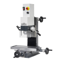
Identification and description of control elements for F1200-F1210 (1.4 kW) models.

16.2 F1200 hs-F1210 hs (2.0 kW) Controls

16.3 F1200-C-F1210-C (1.4 kW) Controls

16.4 F1200-C hs-F1210-C hs (2.0 kW) Controls

16.5 CNC Controls: CC-F1200-CC-F1210 (1.4 kW)

16.5.1 CNC Control Panel Switch Cover

16.6 CNC Controls: CC-F1200 hs-CC-F1210 hs (2.0 kW)

16.6.1 CNC Operating Console Switch Cover

17. Drawings and Legends

17.1 Protective Hood Diagram and Parts

Exploded view and parts list for the protective hood.

17.2 Electronic Hoods (1.4 kW) Diagrams

17.2.1 F1200-F1210 Series Hood Diagram

Exploded view and parts list for the electronic hood of F1200-F1210 series.

17.2.2 CC-F1200-CC-F1210 Hood Diagram

17.3 Milling Head with 1.4 kW Motor Diagram

17.4 Milling Head with 2.0 kW Motor Diagram

17.5 Z-Column with Trapezoidal Spindle Diagram

17.6 Z-Axis Spindle with Trapezoidal Spindle Diagram

17.6.1 F1200-F1210 Series Z-Axis Spindle

Diagram and parts for the Z-axis spindle of F1200-F1210 series.

17.6.2 Z-Axis Spindle for F1200-C;F1210-C;CC Series

17.7 Lateral Z-Axis Drive with Trapezoidal Spindle Diagram

17.8 Cross Slide Support with Trapezoidal Spindle Diagram

17.9 X-Axis Spindle with Trapezoidal Spindle Diagram

17.9.1 F1200-F1210 Series X-Axis Spindle

Diagram and parts for the X-axis spindle of F1200-F1210 series.

17.9.2 X-Axis Spindle for F1200-C;F1210-C;CC Series

17.10 Y-Axis Spindle with Trapezoidal Spindle Diagram

17.10.1 F1200-F1210 Series Y-Axis Spindle

Diagram and parts for the Y-axis spindle of F1200-F1210 series.

17.10.2 Y-Axis Spindle for F1200-C;F1210-C;CC Series

17.11 Z-Column with Ball Screw Diagram

17.12 Z-Axis Spindle with Ball Screw Diagram

17.12.1 F1200-F1210 Series Z-Axis Ball Screw Spindle

Diagram and parts for the Z-axis ball screw spindle of F1200-F1210 series.

17.12.2 Z-Axis Ball Screw Spindle for F1200-C;F1210-C;CC Series

17.13 Lateral Z-Axis Drive with Ball Screw Diagram

17.14 Cross Slide Support with Ball Screw Diagram

17.15 X-Axis Spindle with Ball Screw Diagram

17.15.1 F1200-F1210 Series X-Axis Ball Screw Spindle

Diagram and parts for the X-axis ball screw spindle of F1200-F1210 series.

17.15.2 X-Axis Ball Screw Spindle for F1200-C;F1210-C;CC Series

17.16 Y-Axis Spindle with Ball Screw Diagram

17.16.1 F1200-F1210 Series Y-Axis Ball Screw Spindle

Diagram and parts for the Y-axis ball screw spindle of F1200-F1210 series.

17.16.2 Y-Axis Ball Screw Spindle for F1200-C;F1210-C;CC Series

17.17 Limit Switch for X-Axis Diagram

17.18 Limit Switch for Y-Axis Diagram

17.19 Limit Switch for Z-Axis Diagram

17.20 Machine Control Panel Diagram (1.4 kW Motor)

17.21 Machine Control Panel Diagram (2.0 kW Motor)

17.22 Support Arm for Machine Control Panel Diagram

17.23 Industrial Monitor and Membrane Keyboard Diagram

17.23.1 Industrial Monitor;Keyboard Diagram (1.4 kW Motor)

17.23.2 Industrial Monitor;Keyboard Diagram (2.0 kW Motor)

17.24 Support Arm for Industrial Monitor;Keyboard Diagram

18. Circuit Diagrams

18.1 Circuit Diagram: 1.4 kW Motor

Electrical schematic for the 1.4 kW motor setup.

18.2 Circuit Diagram: 1.4 kW Motor with Safety Cabin

18.3 Circuit Diagram: Monitor;Keyboard (1.4 kW)

18.4 Circuit Diagram: 2.0 kW Motor

18.5 Circuit Diagram: 2.0 kW Motor with Safety Cabin

18.6 Circuit Diagram: Monitor;Keyboard (2.0 kW)

18.7 Stepper Motor with Limit Switch Diagram

18.8 NC-Rotary Table Diagram

18.9 Circuit Diagram Legend

19. Coolant Unit (Optional)

19.1 Setting Up the Coolant Unit

Guidance on positioning and securing the coolant unit.

19.2 Mounting Coolant Unit to Base Cabinet

Instructions for attaching the coolant unit to the machine base cabinet.

19.3 Mounting the Coolant Return Plate

19.4 Coolant Handling Safety Regulations

19.5 Filling the Coolant Unit

19.6 Operating Coolant Unit Without CNC Controller

19.7 Operating Coolant Unit With CNC Controller

19.8 Positioning the Coolant Hose

19.9 Controlling Coolant Flow Valve

19.10 Coolant Unit Drawing and Legend

20. Machine Safety Cabin (Optional)

20.1 Setting Up the Safety Cabin

Instructions for positioning and securing the machine safety cabin.

20.2 Mounting Safety Cabin to Base Cabinet

Steps for attaching the safety cabin to the machine base cabinet.

20.3-20.7 Coolant Operations within Safety Cabin

20.8 Machine Safety Cabin Drawing and Legend

21. Mounting Bracket (Optional)

21.1 Mounting Bracket to Milling Machine

Guidance on attaching the mounting bracket to the milling machine.

21.2 Inserting Drive Unit into Mounting Bracket

21.3 Mounting Bracket Drawing and Legend

22. NC-Rotary Table (Optional)

22.1 Workpiece Clamping on NC-Rotary Table

Instructions for clamping workpieces onto the NC-rotary table.

22.2 Swiveling Worm Shaft

Procedure for swiveling the worm shaft in and out.

22.3 Setting Axial Play of NC-Rotary Table

22.4 Removing the NC Drive Unit

22.5 Setting Worm Shaft Axial Play

22.6 Setting Eccentric Tappet Axial Play

22.7 NC-Rotary Table Drawing and Legend (Part 1)

22.7 NC-Rotary Table Drawing and Legend (Part 2)

WABECO F1210 Specifications

General IconGeneral
BrandWABECO
ModelF1210
CategoryPower Tool
LanguageEnglish

Related product manuals