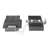
charging current distributor Connection
19
6 Connection
The cable cross-section of the cable for the connection between starter
battery, power relay and consumer battery may not be below 16 mm
2
at ECL-
75 or 25 mm
2
at ECL-100. The cable between the negative pole of the
consumer battery and the vehicle chassis has to be controlled likewise to at
least 16 mm
2
or 25 mm
2
(replace against a stronger cable, if possible).
Warning!
To prevent short circuits, always disconnect the negative terminal of the vehi-
cle's electrical system before working on it.
If the vehicle has an additional battery, its negative terminal should also be dis-
connected.
ECL-75/100 – EC-1500/2000:
➤ Run the control cable from the roof air-conditioning unit to the charging unit
distributor.
➤ Cut off the cable end together with the plug.
Please observe that the cut-off cable end is still long enough for the connection
between charging current distributor and inverter.
➤ Connect the insulated two-core control cable according to the connection diagram on
page 3 (EC-1500), page 4 (EC-2000) with I1 to I4 on the charging current distributor.
➤ Connect with the cut-off cable end the charging current distributor to the inverter.
The plug is screwed with the connection at the inverter.
ECL-100 – EC-2500/3000:
➤ Connect with the two-core cable, according to the connection diagram on page 5 the
roof air-conditioning unit with I2 to I3 at the charging current distributor.
➤ Insert the modular plug of the four-core control cable from the roof air-conditioning
unit into the inverter.
ECL-75 with CA-1000:
➤ Lay the sensing cable (included with the CA-DC, item No.: 4441300084) from the
roof air conditioner to the charging current distributor.
Do not shorten the sensing cable. If the cable is too long, wind it together.
➤ Connect the wires of the sensing cable according to the circuit diagram (see fig. 4,
page 6) with I2 and I3 on the charging current distributor.
➤ Remove the air nozzle unit of the CA-1000.
➤ Insert the three-pole plug of the sensing cable into the socket (3 pole pin strip socket)
on the control PCB of the roof air conditioner (see fig. 6, page 7).
_ECL-75_100.book Seite 19 Freitag, 22. Juli 2005 5:01 17
 Loading...