Do you have a question about the WAGO 750-486 and is the answer not in the manual?
Confirms the documentation applies only to the specified I/O module.
Details changes made in different versions of the manual.
Outlines copyright protections and usage restrictions for the manual.
Explains various symbols used in the manual for warnings and notes.
Defines conventions for decimal, hexadecimal, and binary number representation.
Specifies font usage for paths, menu items, inputs, and buttons.
Covers rights, qualifications, and compliance for using WAGO I/O SYSTEM 750.
Details device specifications, user servicing, and disposal instructions.
Provides essential safety precautions for installation and operation.
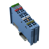
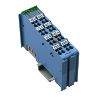
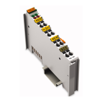
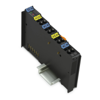
Illustrates the I/O module and its components with a legend.
Describes data contacts, local bus, and power jumper connectors.
Explains the function of status and error LEDs on the module.
States that the I/O module has no operating elements.
Presents a schematic diagram of the I/O module's circuitry.
Lists detailed technical specifications for the device.
Details conformity marking and Ex approvals for the I/O modules.
Lists standards and guidelines met by the I/O modules.
Explains the process image provided by the I/O module.
Describes the implementation and meaning of status bytes for channels.
Details sensor types, standard, and special formats for process data.
Details the procedure for mounting I/O modules on a carrier rail.
Explains the step-by-step process for installing and removing I/O modules.
Provides instructions on connecting conductors using CAGE CLAMP® technology.
Illustrates connection diagrams for 2-wire and 3-wire sensor technologies.
Explains the power supply principles for Ex i modules.
Details power supply concepts specifically for marine applications in Ex i.
Guides users on configuring and parameterizing I/O modules using WAGO-I/O-CHECK software.
Explains user calibration to compensate for component tolerances and improve accuracy.
Describes how to adjust process values using user scaling for required accuracy.
Details how the I/O module responds to various errors and diagnostic functions.
Shows examples of ATEX, IECEx, NEC, and CEC marking for hazardous environments.
Provides special notes and installation regulations for operating in hazardous areas.
Lists rated surge voltages for power supply systems based on IEC 60038.
Explains configuration and parameterization using GSD files for PROFIBUS DP and PROFINET IO.
| Brand | WAGO |
|---|---|
| Model | 750-486 |
| Category | Control Unit |
| Language | English |