Do you have a question about the WAGO 750-461 Series and is the answer not in the manual?
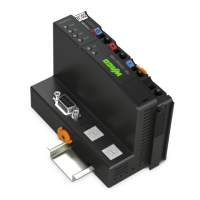
Applicability of this documentation to the I/O module 750-461 and its variants.
Manual copyright and prohibition of unauthorized use or reproduction.
Explanation of warning symbols (DANGER, WARNING, CAUTION, NOTICE) and information symbols used.
Defines notation for decimal, hexadecimal, and binary numbers used in the document.
Explains font usage for paths, menus, input fields, buttons, and keys.
Covers subject to changes, personnel qualifications, and compliance with provisions for the 750 Series.
Details device configuration, non-serviceable parts, and exclusion of liability for unauthorized actions.
Information on proper disposal of electrical and electronic equipment and packaging according to regulations.
Essential safety precautions for installation and operation, including handling energized components and ensuring proper connections.
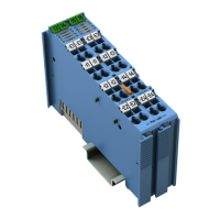
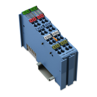
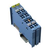
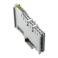
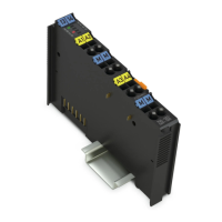
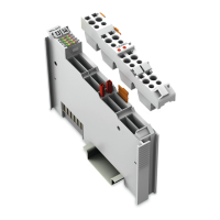
Diagram and legend illustrating the physical layout and key components of the I/O module 750-461.
Details on data contacts (local bus), power jumper contacts, and CAGE CLAMP® connectors for wiring.
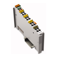
Explanation of status LEDs for each channel indicating operational status and error conditions.
States that the I/O module 750-461 has no operating elements.
Illustrates the internal circuit diagram of the I/O module for understanding its functionality.
Detailed specifications on device data, power supply, communication, inputs, environmental conditions, and connection types.
Lists certifications and approvals granted to the 750-461 I/O modules, including CE, UL, Korea, and Ex approvals.
Details EMC requirements and marine application standards that the I/O modules meet.
Describes process image data for Pt100, Pt1000, and Pt100 with S5-FB250 status variants.
Describes process image data for Ni100, Ni1000 TK6180, and Ni1000 TK5000 variants.
Details process image data for resistance measurement modules (10-1.2 kOhm and 10-5.0 kOhm).
Explains configuration options for the 750-461/003-000 module using WAGO-I/O-CHECK and GSD files.
Describes the NTC 20 kOhm sensor module, including its measuring range and process image data.
Details the procedure for snapping modules onto a carrier rail, including precautions and bus end module requirement.
Instructions for correctly inserting I/O modules into the assembly and onto the carrier rail.
Procedure for safely removing an I/O module from the assembly using the release tab.
Explains how to connect conductors to WAGO CAGE CLAMP® connections, including the use of an actuating tool.
Illustrates the wiring example for connecting two RTD sensors using 2-conductor wiring.
Illustrates the wiring example for connecting two RTD sensors using 3-conductor wiring.
Illustrates marking examples for Europe according to ATEX and IECEx directives, detailing certification and protection types.
Illustrates marking examples for USA (NEC) and Canada (CEC) standards, including explosion protection and temperature class.
Provides critical installation warnings and requirements for explosion protection in hazardous environments.
Details additional requirements for ANSI/ISA Ex installations, including use in specific divisions and connection restrictions.
Explains module configuration and parameterization using GSD files for PROFIBUS DP and PROFINET IO.
Details configuration of the RS-232/RS-485 interface for fieldbus devices.
Details configuration and parameter assignment for PROFIBUS DP and PROFINET IO fieldbus couplers.
| Operating temperature | -25 °C to +60 °C |
|---|---|
| Weight | 150 g |
| Width | 12 mm |
| Number of I/O Modules | 64 |
| Protection Class | IP20 |
| Category | Control Unit |
| Supply voltage | 24 VDC |
| Input signal | 0-10 V, 0-20 mA, 4-20 mA |
| Input resistance | > 100 kΩ |
| Resolution | 12 bits |
| Electrical isolation | 500 VAC |
| Storage temperature | -40 °C to +85 °C |
| Relative Humidity | 95 % (non-condensing) |