WAGO-I/O-SYSTEM 750 Device Description 15
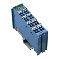
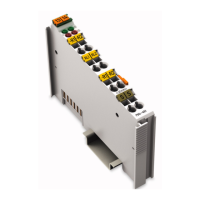
750-461 2AI Pt100/RTD
Manual
Version 1.4.1
Pos: 20 /Alle Serien ( Allgemeine Module)/ Überschriften/Ebene 1/ Gerätebeschreibung - Überschrift 1 @ 3\mod_12337 56084656_21.doc x @ 27096 @ 1 @ 1
3 Device Description
Pos: 21.1.1 /Seri e 750 (WAGO-I/O-SYSTEM)/Gerätebeschr eibung (alte Struktur) /Einleitung/Anwendu ng/AI/Anwendung 750- 04xx AI RTD/NTC nicht para metrierbar @ 24\mod_14520 03630133_21.doc x @ 197738 @ @ 1
The 750-461 I/O module measures resistance at field level or evaluates platinum
or nickel resistance sensors.
The resistance values are converted into temperature values. A microprocessor
in the I/O module linearizes the measured resistance values and converts them
into a numeric value proportional to the temperature of the selected resistance
sensor.
Pos: 21.1.2 /Seri e 750 (WAGO-I/O-SYSTEM)/Gerätebeschr eibung (alte Struktur) /Einleitung/Anwendu ng/AI/Anwendung 75 x-04xx Parametri eren Variante mit Wago IO Check und G SD @ 28\mod_1487243693894_ 21.docx @ 407908 @ @ 1
The WAGO-I/O-CHECK commissioning tool can be used to configure the
required operating mode. The I/O module can also be parameterized via
PROFIBUS and PROFINET device description (GSD file).
The parameterization description can be found in the appendix in Section
“Configuration and Parameterization via GSD File with PROFIBUS DP and
PROFINET IO.”
Pos: 21.1.3 /Seri e 750 (WAGO-I/O-SYSTEM)/Gerätebeschr eibung (alte Struktur) /Einleitung/I/ O-Beschreibung/AI/ I/O-Beschreibung 750-04 xx 2 AI RTD/NTC @ 7\mod_1274420216920_21.doc x @ 56930 @ @ 1
The module has two input channels allowing the direct connection of two 2- or 3-
wire resistance sensors.
For example, two 3-wire sensors can be connected either to +R1, RL1 and −R1
or to +R2, RL2 and −R2.
Pos: 21.1.4 /Seri e 750 (WAGO-I/O-SYSTEM)/Gerätebeschr eibung (alte Struktur) /Einleitung/I/ O-Beschreibung/AI/ I/O-Beschreibung 750-04 xx AI Gemeinsamer Sc hirmanschluss @ 7\mod_12747868 80908_21.docx @ 56960 @ @ 1
Each input channel of a module has a shield (screen) connection (S).
Pos: 21.1.5 /Seri e 750 (WAGO-I/O-SYSTEM)/Gerätebeschr eibung (alte Struktur) /Einleitung/I/ O-Beschreibung/AI/ I/O-Beschreibung 750-04 xx AI Schirmanschlus s Kontakt mit Tragschiene @ 5\mod_1246367742653_21. docx @ 36360 @ @ 1
The shield connection is fed directly to the carrier rail and contact is made
automatically by snapping the module onto the rail.
Pos: 21.1.6 /Seri e 750 (WAGO-I/O-SYSTEM)/Gerätebeschr eibung (alte Struktur) /Einleitung/I/ O-Beschreibung/Allge mein/Verweis auf Kapitel "Anschlüsse" @ 8\ mod_1276775378035_21. docx @ 57956 @ @ 1
The assignment of the connections is described in the “Connectors” section.
Pos: 21.1.7 /Seri e 750 (WAGO-I/O-SYSTEM)/Gerätebeschr eibung (alte Struktur) /Einleitung/I/ O-Beschreibung/Al lgemein/Verweis auf K apitel "Geräte anschließ en" > "Anschlussbeis piel(e)" @ 5\mod_12460152 03281_21.docx @ 36298 @ @ 1
Connection examples are shown in section “Connect Devices” > … >
“Connection Example(s)”.
Pos: 21.1.8 /Seri e 750 (WAGO-I/O-SYSTEM)/Gerätebeschr eibung (alte Struktur)/ Einleitung/LED-An zeige/LED Zustand Betr ieb Kanal @ 5\mod_12453917320 46_21.docx @ 35668 @ @ 1
The operating status of the channels is indicated by a green status LED per
channel.
Pos: 21.1.9 /Seri e 750 (WAGO-I/O-SYSTEM)/Gerätebeschr eibung (alte Struktur)/ Einleitung/LED-An zeige/LED Fehler Kur zschluss/Drahtbr uch/Bereichsüber -/unterschreitung @ 5\mod_124 5391942765_21.doc x @ 35672 @ @ 1
A red error LED per channel indicates a wire break, a short circuit or that the
signal is outside the measuring range.
Pos: 21.1.10 /Seri e 750 (WAGO-I/O-SYSTEM)/Gerätebeschr eibung (alte Struktur )/Einleitung/LED -Anzeige/Verweis auf Kapitel "Anzeigeelement e" @ 5\mod_1246010525000_2 1.docx @ 36194 @ @ 1
The meaning of the LEDs is described in the “Display Elements” section.
Pos: 21.1.11 /Seri e 750 (WAGO-I/O-SYSTEM)/Wichtige Er läuterungen (alte Struk tur)/Sicherhei ts- und sonstige Hinweise/ Hinweis/Hinweis: Potentialeinspei semodul einsetzen! (kei ne LK) @ 3\mod_122649908964 0_21.docx @ 25026 @ @ 1
Use a power supply module!
Use a power supply module for field-side power supply of downstream I/O
modules.
Pos: 21.1.12 /Seri e 750 (WAGO-I/O-SYSTEM)/Gerätebeschr eibung (alte Struktur )/Einleitung/Ver sorgung/Galvanisc he Trennung Feld/Sy stem @ 3\mod_1233756478750 _21.docx @ 27102 @ @ 1
The field voltage and the system voltage are electrically isolated from each other.
Pos: 21.1.13 /Seri e 750 (WAGO-I/O-SYSTEM)/Gerätebeschr eibung (alte Struktur )/Einleitung/Ver sorgung/Anordnung unt er Berücksichti gung der Leistungskontak te beliebig @ 3\mod_12337 56233468_21.docx @ 2709 9 @ @ 1
With consideration of the power jumper contacts, the individual modules can be
arranged in any combination when configuring the fieldbus node.
An arrangement in groups within the group of potentials is not necessary.
Pos: 21.1.14 /Seri e 750 (WAGO-I/O-SYSTEM)/Gerätebeschr eibung (alte Struktur )/Einleitung/Ei nsatzbereich/Ei nsatzbereich 750-xxxx alle Kopp ler/Controller ohne Economy-K oppler @ 3\mod_1232541867468 _21.docx @ 26525 @ @ 1
 Loading...