WAGO-I/O-SYSTEM 750 Process Image 29
750-461 2AI Pt100/RTD
Manual
Version 1.4.1
4.1.3 Pt100 with Status Information for S5-FB250 in the Data
Word
The 750-461/000-200 version outputs the resistance values of the Pt100 sensors
directly. The status information is depicted in bit 0 to bit 2 and the digitalized
measured value in bit 3 to bit 14. When an S5 system is used as the master
controller, this data can be directly evaluated using the FB250 function block.
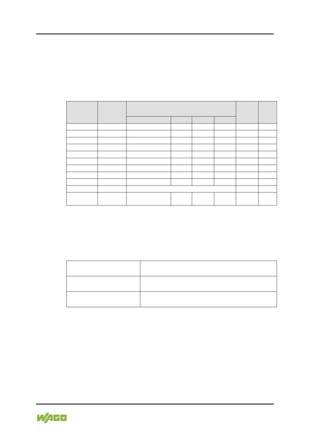
Table 19: Process Image, Pt100
Temperature
°C
Resistance
Ω
Numeric value
2)
with status information
1)
Status
Byte
Hex.
LED
Error
AI 1, 2
1)
Status information: X: not used, F: short circuit, wire break, Ü: overrange
2)
Temperature values below 0 °C are represented in two's complement binary.
“approx.” indicates non-calibrated data.
4.2 I/O Modules with Ni Resistance Sensors
Table 20: I/O Modules with Ni Resistance Sensors
Evaluation Ni100
Measuring range: −60 °C to +250 °C
Evaluation Ni1000 TK6180
Measuring range: −60 °C to +250 °C
Measuring range: −30 °C to +122 °C
 Loading...