34 Process Image WAGO-I/O-SYSTEM 750
750-461 2AI Pt100/RTD
Manual
Version 1.4.1
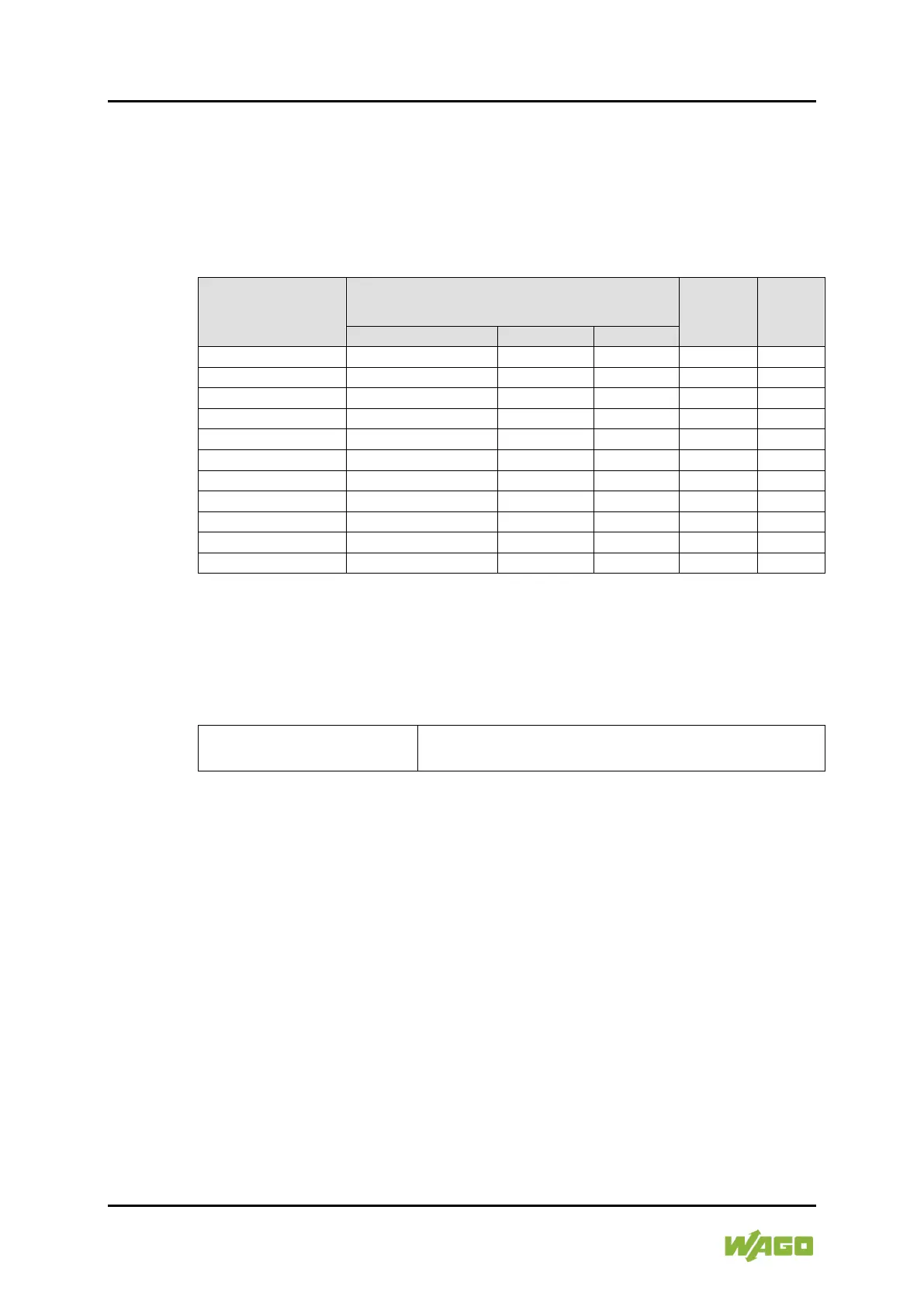
4.3.2 Resistance Measurement 10 Ohm to 5.0 kOhm
The 750-461/000-007 version outputs the resistance values of the sensors
directly. The resistance values are displayed at a resolution of 1 digit per 0.5 Ω in
one word (16-bit). The possible numeric range corresponds to the defined
measurement range of 10 Ω to 5.0 kΩ.
Table 26: Process Image (10 Ω to 5.0 kΩ)
Resistance
Ω
Numeric value
Status
Byte
Hex.
LED
Error
AI 1, 2
“approx.” indicates non-calibrated data.
Pos: 24.4 /Serie 750 (W AGO-I/O-SYSTEM)/Prozessabbild Loka lbus/AI/Prozess abbild 750-0461 Parametri erbare Variante @ 28\mod _1487251458162_21.doc x @ 407911 @ 2 @ 1
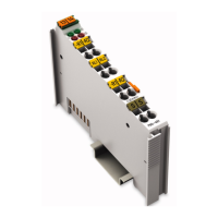
4.4 Configurable I/O Module 750-461/003-000
Table 27: Configurable I/O Module
Default setting: Pt100 configurable
Measuring range: −200 °C … +850 °C
The operating mode of the I/O module version 750-461/003-000 can be freely
configured using the WAGO-I/O-CHECK commissioning tool. The default setting
is Pt100. In this mode the I/O module has the same process values as the
standard I/O module 750-461.
The WAGO-I/O-CHECK commissioning tool can be used to configure the
required operating mode. The I/O module can also be parameterized via
PROFIBUS and PROFINET device description (GSD file).
The parameterization description can be found in the appendix in Section
“Configuration and Parameterization via GSD File with PROFIBUS DP and
PROFINET IO.”
The parameter dialog in WAGO-I/O-CHECK presents optional fields for the
settings of this I/O module:
 Loading...