WAGO-I/O-SYSTEM 750 List of Figures 61
750-461 2AI Pt100/RTD
Manual
Version 1.4.1
Pos: 45 /Dokumentation al lgemein/Verzeic hnisse/Abbildungs verzeichnis - Übersc hrift oG und Verzeichni s @ 3\mod_1219222916765_21. docx @ 21080 @ @ 1
List of Figures
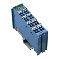
Figure 1: View ...................................................................................................... 16
Figure 2: Data Contacts ....................................................................................... 17
Figure 3: CAGE CLAMP
®
Connectors ................................................................. 18
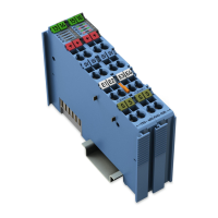
Figure 4: Display Elements .................................................................................. 19
Figure 5: Schematic Diagram .............................................................................. 20
Figure 6: Insert I/O Module (Example) ................................................................. 38
Figure 7: Snap the I/O Module into Place (Example) .......................................... 38
Figure 8: Removing the I/O Module (Example) ................................................... 39
Figure 9: Connecting a Conductor to a CAGE CLAMP
®
...................................... 40
Figure 10: Example Connection 2 × RTD, 2-wire ................................................ 41
Figure 11: Example Connection 2 × RTD, 3-wire ................................................ 42
Figure 12: Marking Example According to ATEX and IECEx .............................. 44
Figure 13: Text Detail – Marking Example According to ATEX and IECEx ......... 44
Figure 14: Marking Example for Approved Ex i I/O Module According to ATEX
and IECEx .................................................................................................. 46
Figure 15: Text Detail – Marking Example for Approved Ex i I/O Module
According to ATEX and IECEx ................................................................... 46
Figure 16: Marking Example According to NEC .................................................. 48
Figure 17: Text Detail – Marking Example According to NEC 500 ...................... 48
Figure 18: Text Detail – Marking Example for Approved Ex i I/O Module
According to NEC 505 ................................................................................ 49
Figure 19: Text Detail – Marking Example for Approved Ex i I/O Module
According to NEC 506 ................................................................................ 49
Figure 20: Text Detail – Marking Example for Approved Ex i I/O Modules
According to CEC 18 attachment J ............................................................ 50
Figure 21: Example of the PROFIBUS DP Fieldbus Coupler/Controller
Configuration Dialog ................................................................................... 56
Figure 22: Example of the 750-370 Fieldbus Coupler Configuration Dialog ........ 56
Figure 23: Example of the 750-375(/025-000) and 750-377(/025-000)
Fieldbus Coupler Configuration Dialog
....................................................... 57
Pos: 46 /Dokumentation al lgemein/Glieder ungselemente/---Sei tenwechsel--- @ 3\mod_122110804 5078_0.docx @ 21810 @ @ 1
 Loading...