EasyManua.ls Logo

WAGO 750-557/040-000 User Manual

WAGO 750-557/040-000
52 pages
To Next Page IconTo Next Page
Page #1 background imageLoading...
Page #1 background image
Manual
WAGO-I/O-SYSTEM 750 XTR
750-557/040-000
4AO +/-10V DC /XTR
4-Channel Analog Output Module, ±10 VDC /XTR
Version 1.3.0

Table of Contents

Question and Answer IconNeed help?

Do you have a question about the WAGO 750-557/040-000 and is the answer not in the manual?

WAGO 750-557/040-000 Specifications

General IconGeneral
BrandWAGO
Model750-557/040-000
CategoryControl Unit
LanguageEnglish

Summary

Notes about this Documentation

Validity of this Documentation

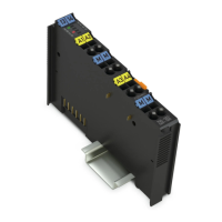
Specifies the applicability of the documentation to the I/O module 750-557/040-000.

Copyright

Details the copyright protection and usage restrictions for the manual.

Symbols

Number Notation

Font Conventions

Important Notes

Legal Bases

Covers legal aspects like subject to changes and personnel qualifications.

Personnel Qualifications

Specifies the required qualifications for personnel handling the devices.

Use of the 750 Series in Compliance with Underlying Provisions

Explains how to use the 750 series in compliance with provisions and environmental conditions.

Technical Condition of Specified Devices

Details that devices are pre-configured and not user-serviceable.

Safety Advice (Precautions)

DANGER: Do not work on devices while energized!

Warning to switch off power before any installation or maintenance work.

DANGER: Install device in only one suitable enclosure!

Mandates installation in a suitable enclosure with specific requirements.

CAUTION: Do not touch hot surfaces!

NOTICE: Protect the components against materials having seeping and insulating properties!

NOTICE: Do not reverse the polarity of connection lines!

NOTICE: Avoid electrostatic discharge!

NOTICE: Use only direct current (DC) for insulation testing!

Device Description

NOTICE: Do not exceed maximum values via power contacts!

Warns against exceeding current limits on power jumper contacts.

Note: Mixed operation

Notes on mixed operation of standard/XTR modules requiring electrical isolation.

Note: Increased interference!

View

Connectors

Data Contacts/Local Bus

Explains communication via local bus using data contacts.

Power Jumper Contacts/Field Supply

CAGE CLAMP® Connectors

Display Elements

Schematic Diagram

Technical Data

Device Data

Lists physical dimensions, weight, and degree of protection.

Power Supply

Details voltage supply, current consumption, and surge voltage ratings.

Communication

Specifies data width for communication.

Outputs

Connection Type

Mechanical Conditions

Climatic Environmental Conditions

Approvals

Information

Provides information on how to find detailed approval references.

Standards and Guidelines

Process Image

Mapping of process data in the process image of fieldbus systems

Explains how process data is represented in the process image.

Mounting

Mounting Sequence

Details the procedure for snapping modules onto the carrier rail.

Don't forget the bus end module!

Reminds to install the bus end module for proper data transfer.

Inserting and Removing Devices

Inserting the I/O Module

Step-by-step guide for inserting an I/O module onto the carrier rail.

Removing the I/O Module

Connect Devices

Connecting a Conductor to the CAGE CLAMP®

Explains how to connect conductors to CAGE CLAMP® terminals.

Connection Example

Use in Hazardous Environments

Marking Configuration Examples

Shows marking examples for ATEX and IECEx compliance.

Marking for Europe According to ATEX and IECEx

Provides detailed marking example for European ATEX and IECEx certifications.

Marking for the United States of America (NEC) and Canada (CEC)

Installation Regulations

Special Notes Regarding Explosion Protection

Lists critical warning notices for explosion protection.

Special Notes Regarding ANSI/ISA Ex

Related product manuals