62 List of Tables WAGO-I/O-SYSTEM 750
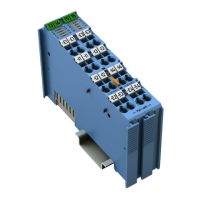
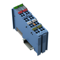
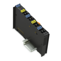
750-461 2AI Pt100/RTD
Manual
Version 1.4.1
Pos: 47 /Dokumentation al lgemein/Verzeic hnisse/Tabellen verzeichnis - Übersc hrift oG und Verzeichnis @ 3\mod_ 1219222958703_21. docx @ 21084 @ @ 1
List of Tables
Table 1: Variants .................................................................................................... 5
Table 2: Number Notation ...................................................................................... 9
Table 3: Font Conventions ..................................................................................... 9
Table 4: Legend for Figure “View” ....................................................................... 16
Table 5: Legend for Figure „CAGE CLAMP
®
Connectors“ .................................. 18
Table 6: Legend for Figure “Display Elements” ................................................... 19
Table 7: Technical Data — Device ...................................................................... 21
Table 8: Technical Data – Power Supply ............................................................. 21
Table 9: Technical Data – Power Supply ............................................................. 21
Table 10: Technical Data, Communication .......................................................... 21
Table 11: Technical Data – Inputs (RTD Model 750-461) ................................... 22
Table 12: Technical Data – Inputs for 750-461/020-000 Model ........................... 22
Table 13: Technical Data – Climatic Environmental Conditions .......................... 23
Table 14: Technical Data – Field Wiring .............................................................. 23
Table 15: Technical Data – Data Contacts .......................................................... 23
Table 16: I/O Modules with Pt Resistance Sensors ............................................. 27
Table 17: Process Image, Pt100, with Wire Break Diagnostics ........................... 28
Table 18: Process Image, Pt1000, with Wire Break Diagnostics ......................... 28
Table 19: Process Image, Pt100 ......................................................................... 29
Table 20: I/O Modules with Ni Resistance Sensors ............................................. 29
Table 21: Process Image, Ni100, with Wire Break Diagnostics ........................... 30
Table 22: Process Image, Ni1000 TK6180, with Wire Break Diagnostics ........... 31
Table 23: Process Image, Ni1000 TK5000, with Wire Break Diagnostics ........... 32
Table 24: I/O Modules for Resistance Measurement .......................................... 33
Table 25: Process Image (10 Ω to 1.2 kΩ)
.......................................................... 33
Tabl
e 26: Process Image (10 Ω to 5.0 kΩ) .......................................................... 34
Table 27: Configurable I/O Module ...................................................................... 34
Table 28: Setting Options for I/O Module 750-461/003-000 ............................... 35
Table 29: I/O Module 750-461/003-000, Offset and Gain Values ........................ 35
Table 30: I/O Module 750-461/003-000, Input Fields for Hardware Matching ..... 36
Table 31: I/O Module for NTC Resistance Measurement .................................... 36
Table 32: Process Image for Version 750-461/020-000 ...................................... 36
Table 33: Description of Marking Example According to ATEX and IECEx......... 45
Table 34: Description of Marking Example for Approved Ex i I/O Module
According to ATEX and IECEx ................................................................... 47
Table 35: Description of Marking Example According to NEC 500...................... 48
Table 36: Description of Marking Example for Approved Ex i I/O Module
According to NEC 505 ................................................................................ 49
Table 37: Description of Marking Example for Approved Ex i I/O Modules
According to NEC 506 ................................................................................ 49
Table 38: Description of Marking Example for Approved Ex i I/O Modules
According to CEC 18 attachment J ............................................................ 50
Table 39: Configuration PROFIBUS DP and PROFINET IO (750-370)............... 55
Table 40: Configuration PROFINET IO (750-375(/025-000), 750-377
(/025-000))
................................................................................................
.. 55
Table 41: Specific Module / Channel Parameters for 75x-652 ............................ 57
Table 42: General Module / Channel Parameters ............................................... 59
 Loading...