Assembly and Installation
4
Assembly and Installation
Instructions
This section covers the assembly and installation of
the A54 Deck Height Adjuster.
1. Remove the deck from the tractor.
2. Remove the carrier frame from deck housing
by removing the hitch pins from the deck height
pins and lifting the carrier frame off the deck
housing.
3. Drill out the eight (8) pilot mount holes on the
deck housing to 1/4” and deburr the holes.
NOTE: For DC48 decks, there are only four (4)
front mount holes to drill out. The rear mount
holes are capped with four (4) factory installed
hex bolts that need to be removed.
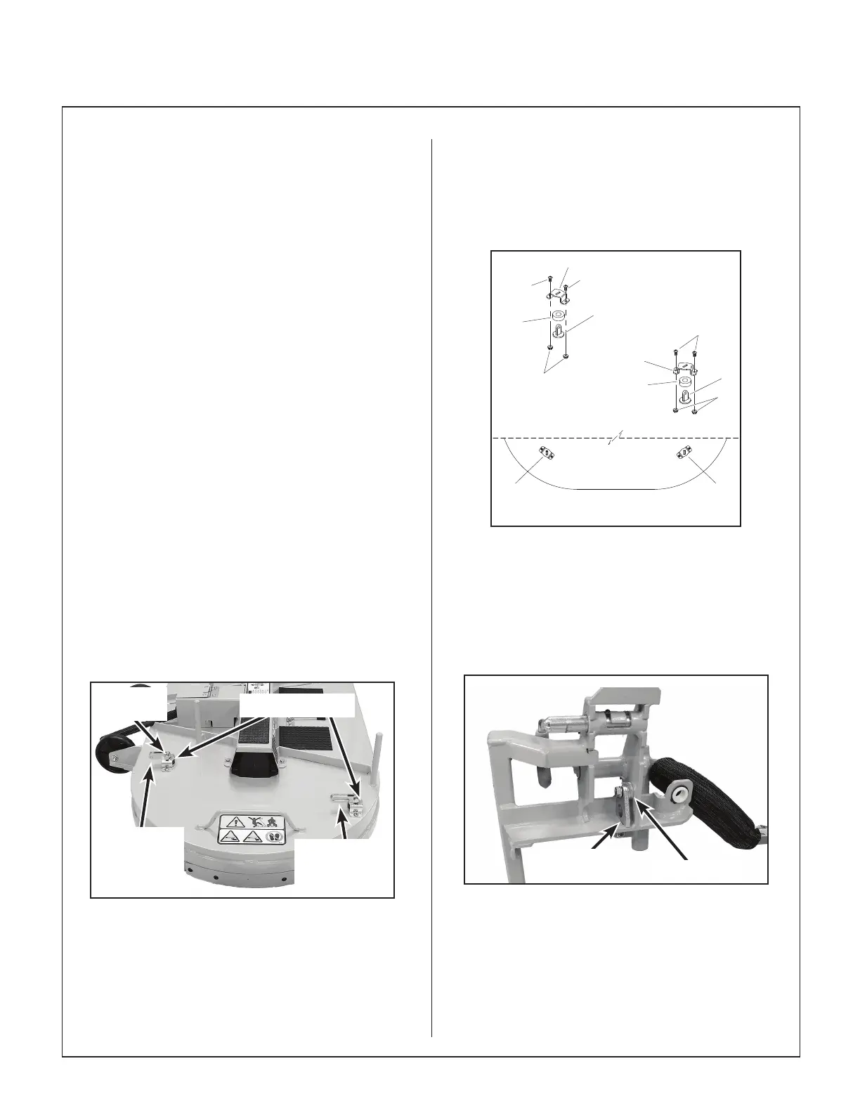
4. There are four (4) Lift Saddles (#5, P/N 7211-9)
that come installed with either slotted Front Lift
Links (#19) or round Rear Lift Links (#20). The
heads of the bolts that secure the Lift Links to
the Lift Saddle need to face out. Install the Lift
Saddles on the housing using eight (8) 1/4-20 x
1/2 button head bolts (F717) and 1/4-20 ange
top lock nuts (F569). Fully tighten.
NOTE: For DC48 decks, the rear bolts are
secured by a threaded insert in the deck.
Rear Lift
Links with
Round
Opening
Front Lift Links
with Slotted
Opening
Lift Saddles
Bolt Head
Out
Lift Saddles Installed (DM48 Shown)
NOTE: For DM52 decks, the Lift Saddles for
the front will need to be replaced with the RH
Lift Saddle (P/N 7211-18) and the LH Lift Sad-
dle (P/N 7211-19) to provide a correct mount-
ing angle. Transfer the Lift Links from the stan-
dard Lift Saddles before installing them.
F717
F717
F717
43
43 44
44
39
39
6
6
F569
F569
DM52 FRONT ANGLED BRACKETS
TOP VIEW
(REF)
DM52 Angled Lift Saddles
5. On the LH side of the carrier frame, install
nger tight the Inner Retainer (#35, P/N 7211-
14) with a 1.0 x 5/16 x 5/16 Spacer (#36, P/N
6325-14) using a 5/16-18 x 1-1/8 hex bolt
(F645) and a 5/16-18 ange top lock nut
(F551). Do not fully tighten.
Spacer (#36)
Inner Retainer
In Slot
Inner Retainer Installed (LH Shown from
Under the Carrier Frame)