Do you have a question about the Wallbe LEO and is the answer not in the manual?
Welcome and overview of wallbe® charging stations, emphasizing compliance with IEC 61851-1.
Defines the charging system's purpose for private/semiprivate areas and restrictions on use.
Critical safety guidelines covering user life, health, and equipment during operation and handling.
Advises consultation with manufacturers for individuals with pacemakers or ICDs regarding radiation.
Provides essential safety steps before and during charging, including unwinding cables and checks.
Covers electrical protection, detailed installation tests (PE, insulation, faults, RCDs), and inspection requirements.
Identifies protective components and outlines procedures for checking their integrity.
Describes the LED indicators, buttons, and the process for starting and stopping charging.
Key requirements for operating the Wallbox, including mounting, power supply, and cable diameter.
Lists all items included in the Wallbox package, such as mounting hardware and documentation.
Provides detailed steps and prerequisites for securely mounting the Wallbox onto a wall.
Details the procedure for attaching the Wallbox to a column using the provided mounting plate.
Guides through connecting the power supply, setting charging current, and external control options.
Covers initial power-up, LED status, wake-up options, and external block indicators.
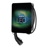
The wallbe® LEO Wallbox is a charging station designed for convenient, safe, and standard-compliant charging of electric vehicles, adhering to IEC 61851-1, charging mode 3. It is intended for use in private and semi-private areas, such as private properties, corporate parking areas, or depots. The system is exclusively for charging electric vehicles and operates with plug-and-socket connectors in accordance with IEC 62196. It is compatible with TT, TN-C, and TN-C-S networks but must not be operated in IT networks. The wallbe® LEO is not suitable for charging vehicles with outgassing batteries (e.g., lead-acid batteries). It functions as an individual station without a superordinate control system and is designed for stationary installation only.
The wallbe® LEO charging station facilitates the charging of electric vehicles. It is equipped with integrated AC and DC residual-current detection for safety. The DC residual-current detection switches off the charging system if a residual current greater than or equal to 6 mA DC is detected. The AC residual-current detection acts as a convenience function, switching off the system if a residual current greater than 30 mA AC is detected, with a tripping time of less than 40 ms. These features are designed to enhance safety during the charging process. The charging current of the Wallbox can be adjusted from 6 A to 16 A using a rotary switch, allowing users to set it in accordance with the building's circuit breakers.
The system can be operated via a single pushbutton/LED combination. An optional external blocking device, such as a key switch, can be connected to the internal interface to control access to the charging process. The LED indicates the operating state of the charging system, providing visual feedback to the user. The charging process starts automatically when the charging coupler is plugged into the vehicle and the vehicle requests a charge. If an external blocking device is in use, charging will only commence once the Wallbox has been enabled by this external device.
To ensure safe operation, users must read the instruction manual carefully and follow all instructions. All persons working on or using the charging system must be familiar with the operating manual and adhere to safety regulations. The equipment documentation should be kept accessible to operators, and unauthorized persons should not have access to the system.
The Wallbox should be mounted vertically and, if possible, in a location not directly exposed to rain, hail, or direct sunlight to prevent damage or overheating. The supply voltage's individual phases must be protected with residual current devices and circuit breakers. Only multi-wire cables should be used for power supply, with a diameter between 9 mm and 17 mm.
The charging process begins automatically once the charging coupler is plugged into the vehicle and the vehicle requests a charge. If the Wallbox is in standby mode, plugging in the charging cable will automatically switch it to ready mode, indicated by a green LED. Alternatively, pressing the button (without a connected vehicle) will also switch it to ready mode.
Stopping the charging process cannot be done via the button on the Wallbox itself. There are three methods to stop charging:
Maintenance and electrical installation of the charging system must only be performed by qualified electricians authorized by the operator. These electricians must have read and understood the equipment documentation and comply with its instructions, including the 5 safety rules for working with electrical installations (isolate, secure against reactivation, check absence of voltage, ground and short-circuit, cover or block off live parts).
Before each use, a visual inspection of the protective devices (housing, connecting line, charging coupler) for damage is required. Any damaged parts must be repaired or replaced to maintain functional properties. Safety identifications, danger signs, and safety lights must remain easily visible and effective.
Regular electrical function tests, in accordance with national regulations, should be performed by a qualified electrician. This includes:
The housing of the charging system must always be kept closed. During operation, extension cables, cable reels, multisocket power strips, or travel adapters must not be used. Objects must not be inserted into the charging coupler, and plug-in connections must be protected against moisture and liquids. The charging system or coupler should never be immersed in water. The charging coupler must not be disconnected from the vehicle during charging. wallbe® only takes responsibility for the charging system in its delivered condition and for work performed by skilled wallbe® personnel.
| Housing Material | Plastic |
|---|---|
| Charging Modes | Mode 3 |
| Ingress Protection | IP54 |
| Connector Type | Type 2 |
| Protection Features | Overcurrent, Overvoltage, Short Circuit, Overheating |
| Operating Temperature | -25°C to +50°C |