FX66, FX85, FX110, FX140
PTO Skidding Winch
Attaching Winch to Tractor
19
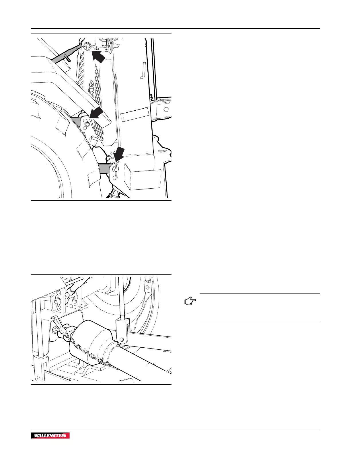
Fig. 8 – Winch Attached
9. Slide the collar back on the PTO shaft yoke. Align the
splines and slide the yoke on the tractor PTO.
10. Release the collar and make sure the locking pin clicks into
position.
11. Attach the shield anchor safety chain to an adjacent frame
member. The chain keeps the integral journal shield from
spinning.
Fig. 9 – PTO Shaft Installed
12. Raise winch support legs to the storage position. Insert
snap lock pins.
13. Start the tractor and slowly raise the machine up through
its working range to make sure the telescoping portion of
the PTO shaft does not bottom out.
To detach winch from the tractor, reverse the above steps.
4.1 Winches with Remote Control
FX85R, FX110R and FX140R models include a wireless remote
winch control. The system consists of a hand-held transmitter
control and a receiver mounted on the winch.
For the remote to function, the following electrical and hydraulic
connections to the winch must be made.
Electrical Connection
• A 12 VDC, 1.5 amp power source is required from the
tractor electrical system.
• The white wire from the receiver should be connected to
positive, black to ground.
• Connectors are not supplied on the wire ends. Wire ends
are supplied bare to permit different adaptations.
Hydraulic Connection
• A valve on the winch controls the winch clutch. The system
is designed for an open-center hydraulic system. Oil flow
required is 1–2 gpm (3.8–7.5 L/m). This oil flow rate
provides the best starting/stopping speeds to prolong rope
life.
• The 1/2" pressure and return hoses have quick-disconnect
ends and are connected to the tractor rear remote power
supply.
• The hoses have colored, protective caps to indicate
function. Red is pressure and blue is return.
In the event pressure and return hoses are not
identifiable, check the connection on the control
valve. 'R' is indicated on the return port. 'P' is
indicated on the pressure port.