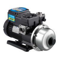
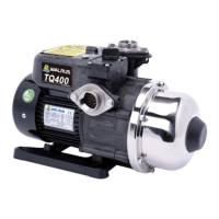
This document outlines the procedure for replacing the mechanical seal of a Walrus HQ800(H) pump, providing a detailed, step-by-step guide for both removal and assembly. The HQ800(H) appears to be a self-priming peripheral pump, likely used for water transfer or boosting applications in residential or light commercial settings, given its common design for such uses. The "H" in the model name might indicate a high-head version or a specific variant, but the core function remains consistent with the HQ800 series.
Function Description:
The Walrus HQ800(H) pump is designed to move fluids, typically water, by creating pressure. Its mechanical seal is a critical component that prevents leakage of the pumped fluid along the pump shaft where it enters the pump casing. The seal consists of stationary and rotary parts, often made of ceramic and carbon or other durable materials, which create a tight barrier while allowing the shaft to rotate freely. The replacement process detailed in this manual ensures the pump maintains its sealing integrity, preventing fluid loss and protecting the motor from water ingress, which is essential for the pump's efficient and safe operation. The pump's design, featuring multiple impellers and intermediate chambers, suggests it is a multi-stage pump, capable of generating higher pressures compared to single-stage designs, making it suitable for applications requiring significant head.
Important Technical Specifications (Inferred from the manual):
While specific numerical specifications like flow rate, head, motor power, or voltage are not explicitly stated in this maintenance guide, several technical aspects can be inferred from the visual information and procedural steps:
- Pump Type: The visual evidence of multiple impellers and intermediate chambers strongly suggests a multi-stage centrifugal or peripheral pump design. This configuration is typically chosen for applications requiring higher pressure (head) rather than extremely high flow rates.
- Mechanical Seal Type: The mechanical seal consists of a stationary part (rubber housing with a ceramic or similar ring) and a rotary part (often carbon or silicon carbide). The replacement process highlights these two main components. The use of a ceramic part is explicitly mentioned.
- Fasteners: The pump utilizes Allen screws for securing the main casing components and stud bolts for assembling the pressure tank and other sections. The manual specifically notes different sizes of stud bolts, indicating a precise assembly requirement.
- Materials (Inferred): The pump casing appears to be made of a robust material, possibly cast iron or a durable engineering plastic for the main body, with stainless steel or chrome-plated components for the pressure tank and internal parts like sleeves and impellers, given the shiny metallic appearance. The "CHROME VANADIUM" marking on the wrench in step 2 of removal suggests the use of durable fasteners.
- Lubrication: Water is recommended as a lubricant during the assembly of the mechanical seal, indicating that the seal components are designed to operate effectively with water as the primary medium and that dry installation could cause damage.
- Pressure Tank: The pump includes a pressure tank, which is a common feature in domestic water supply systems to maintain pressure and reduce pump cycling. The installation of an O-ring for this tank emphasizes the importance of a watertight seal.
Usage Features (Inferred from the maintenance process):
The maintenance guide primarily focuses on the mechanical seal replacement, but this process indirectly reveals aspects of the pump's design for usability and serviceability:
- Modular Design: The pump appears to have a modular construction, allowing for the disassembly of specific sections (impellers, sleeves, intermediate chambers, pressure tank) to access internal components like the mechanical seal. This modularity simplifies maintenance and repair.
- Standard Tooling: The procedure requires common tools such as an Allen wrench and a standard wrench, indicating that specialized tools are not extensively needed for this particular maintenance task, making it accessible for technicians.
- Clear Assembly Order: The manual emphasizes placing components "in order" during both removal and assembly, which is a crucial feature for ensuring correct reassembly and proper pump function. This suggests that the pump's internal components have a specific sequence that must be followed.
- Lubrication Requirement: The instruction to "Spray water on the shaft as lubrication" during mechanical seal assembly highlights a specific operational requirement for proper seal seating and to prevent damage during installation.
- Visual Cues for Assembly: The use of red circles to indicate the placement of shorter stud bolts (step 10 of assembly) is a helpful visual cue, simplifying the reassembly process and reducing the chance of errors.
Maintenance Features:
The document itself is a maintenance guide, and as such, it directly illustrates several maintenance-related features:
- Detailed Step-by-Step Instructions: The guide provides clear, numbered steps with accompanying images for each stage of the mechanical seal replacement, making the process easy to follow even for those with moderate technical experience.
- Visual Aids: High-quality photographs for each step are invaluable, showing the exact components and actions required, which significantly reduces ambiguity and potential errors.
- Component Identification: The guide clearly identifies key components such as "Allen wrench," "stud bolt," "impellers," "sleeves," "intermediate chambers," "rotary parts of mechanical seal," "ceramic parts," "stationary part (rubber)," "O-ring," and "pressure tank."
- Emphasis on Order: The repeated instruction to "place all impellers, sleeves and intermediate chambers in order" during both removal and assembly underscores the importance of maintaining the correct sequence of internal components for proper pump operation.
- Specific Fastener Guidance: The instruction to "Identify different sizes of stud bolts" and "Install shorter stud bolts on the red circled places" demonstrates attention to detail in assembly, ensuring that the correct fasteners are used in their designated locations.
- Cleanliness Requirement: The instruction to "make sure it is clean" when installing the O-ring onto the pressure tank highlights the importance of cleanliness in maintaining effective seals and preventing premature wear or failure.
- Focus on Critical Components: The guide specifically targets the mechanical seal, a common wear part in pumps, indicating that this component is designed to be replaceable, extending the overall lifespan of the pump.
- Safety Considerations (Implied): While not explicitly stated as safety instructions, the use of proper tools (wrenches) and the systematic disassembly/assembly process inherently promote safe working practices by preventing damage to components or injury to the technician. The need to tighten fasteners properly (e.g., "Tighten up the stud bolt," "Tighten up the stud bolts") ensures the pump's structural integrity and leak-free operation after maintenance.