Instruction Handbook KL
Chapter 4
BA KL V11 en 10/2014 page 4-2
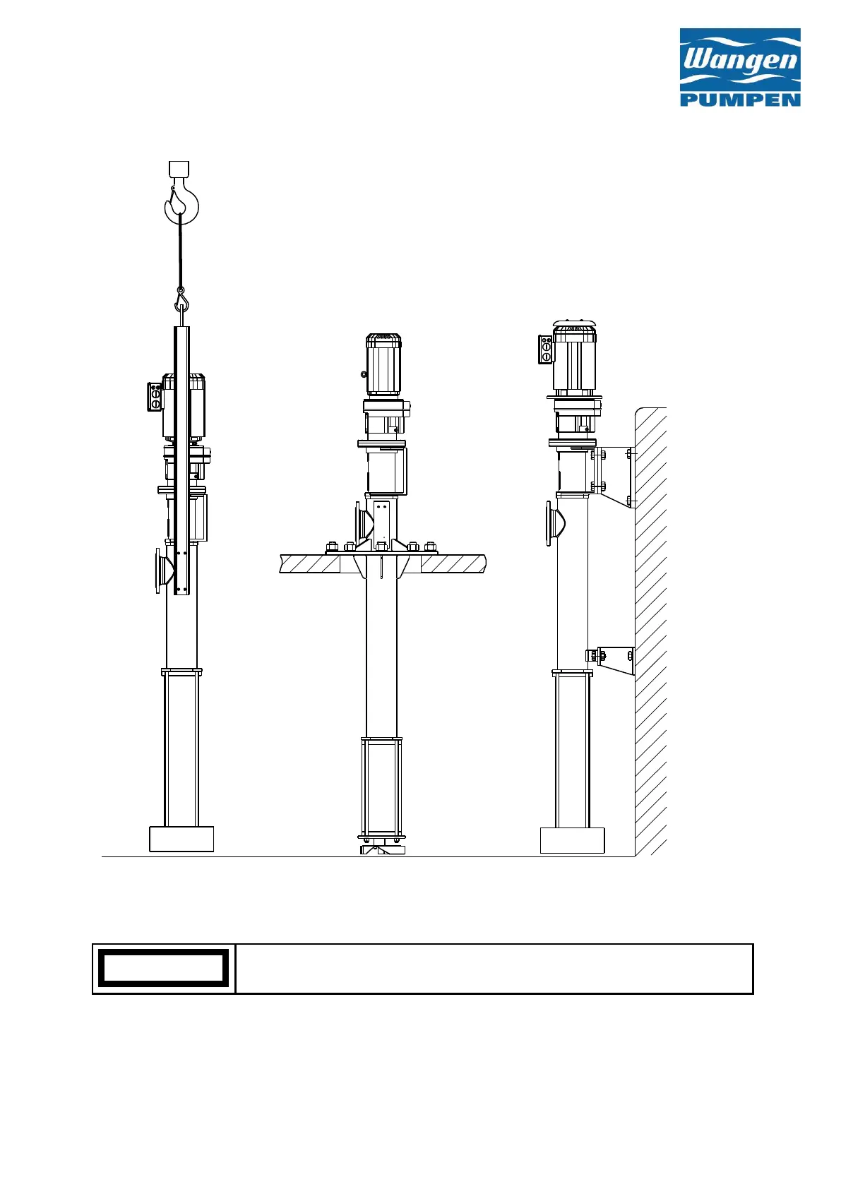
The adjacent figure shows attachments for different forms of the KLT pump.
Use suitable screw connections and concrete anchors for the connections in the concrete
of the silo wall.
In so doing, use the hole diameters of the flanges, brackets and drill holes on the bearing
block as a basic orientation.
Fig. 4-1 KLT with hanging bracket Fig. 4.2 KLT with mounting flange 4.3 KLT fixed to bearing chair and bracket
 Loading...