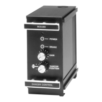
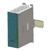
Tension control system X2DRV
29/08/2012
X2DRV Installation & Operation Manual Page 5 of 5
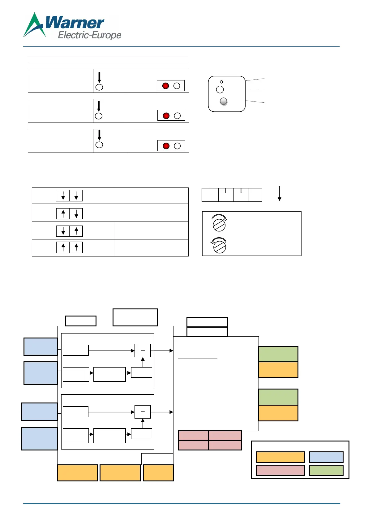
10. (Optional): The frequency adjustment changes the modulation frequency to eliminate brake “hum” or “howl” when the brake is
stationary. The frequency is factory set and normally requires no adjustments. Set the frequency as describe below with the red
switches below the chassis:
11. Double check all wiring connections per figure 2 and insure all terminals are tight
Note: If an over-load occurs (current 4A more) the Driver output will shut down and the red LED will turn ON. To reset the system remove
power to the Driver and turn it on again.
X2DRV Block Diagram:
“Teachable Span” calibration procedure
With the Auxiliary wired to Ana1
or Ana2
Press Cal button >5s.
Put Min to Ana1 or Ana2
Short press to valid: Min is learnt
Put Max to Ana1 or Ana2
Short press to valid: Max is
learnt and calibration is done
Set 0: Between 250 and 750 HZ
Set 1: Between 1000 and 3000 HZ
Set 2: Between 2500 and 7500 HZ
Set 3: Between 4250 and 10
(default)
V/I
F1
F2
Red LED on
Slow flashing
Figure 6: Anti-residual setting and calibration
Cal
Cal
Cal
>5s
Quick flashing
Turn the trim pot clockwise
to increase the frequency
counterclockwise to decrease
Power Layers
OUTPUT Control:
Pulse width modulated 4 Amps
with Anti-residual Mode
24V DC +/- 5%, 4A
Frequency
or 4-20mA
or 4-20mA
or 4-20mA
or 4-20mA
Open Loop Digital Control
X Gain
Prop.2
Open Loop Digital Control
X Gain
Prop.1
Hardware interface
Digital Input (Active low)
Analog Input
Analog Output
Setting
Cal
AntiR
LED
Potentiometer for Anti-residual setting
State LED
Auxiliary Input Calibration: Ana1 & Ana2
 Loading...