EasyManua.ls Logo

Warner Electric X2DRV - User Manual

Warner Electric X2DRV
5 pages
Print Icon
To Next Page IconTo Next Page
Loading...
X2DRV
Installation & Operation Manual
Introduction:
The x2DRV
is a solid state electronic control that will accept a variety of input signals and provides to the brake an output current a
proportional to the input. This double channel driver can be operated by a remote potentiometer, a voltage or a current
The x2DRV is a
24VDC double channel driver, 4Amps current capability.
When associated with an xCTRL, power supply, Input and (Communication) will be made by the internal connector.
This manual has been designed to cover the full range of
Tension control system X2DRV
Installation & Operation Manual
24VDC double channel driver, 4Amps current capability.
This manual has been designed to cover the full range of
installation, start-
up and operation of your tension control system.
Figure 1:x2DRV housing dimensions
29/08/2012
Page 1 of 5
is a solid state electronic control that will accept a variety of input signals and provides to the brake an output current a
nd voltage
proportional to the input. This double channel driver can be operated by a remote potentiometer, a voltage or a current
loop input.
When associated with an xCTRL, power supply, Input and (Communication) will be made by the internal connector.
up and operation of your tension control system.
Question and Answer IconNeed help?

Do you have a question about the Warner Electric X2DRV and is the answer not in the manual?

Summary

Introduction to the X2 DRV Tension Control System

X2 DRV Housing Dimensions

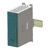
Diagram showing the physical dimensions of the X2DRV unit.

X2 DRV Technical Specifications and General Information

Ratings and Compliance

Details the electrical ratings, operating temperature, and compliance standards for the X2DRV.

General Information and Supported Brakes

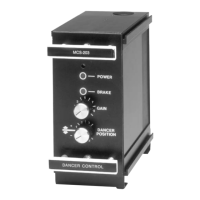
Provides general guidance on control chassis placement and lists compatible Warner brake models.

Hardware Pin Out Description

Detailed description of each pin on the X2DRV hardware interface and its function.

System Wiring and Configuration

Wiring Precautions and Safety Warnings

Essential precautions and warnings regarding electrical voltage and proper wiring practices.

X2 DRV Wiring Diagram

Illustrates the wiring connections for the X2DRV with one or two brakes.

Power Supply Wiring

Instructions for connecting the 24V DC power supply to the X2DRV.

Input Type Selection

Guide to selecting the input signal type (0-10V or 4-20mA) using internal switches.

Output Type Selection

Guide to selecting the output control type (Voltage or Current) using internal switches.

Advanced Setup and Calibration

Setting the Anti-residual

Procedure for adjusting the anti-residual to ensure proper brake armature release.

Voltage Output vs. Anti-residual Control

Graphical representation of the relationship between output voltage and anti-residual.

NPN Input Configuration (ON;OFF Pins)

Details on configuring the ON/OFF pins as NPN type inputs for brake control.

Open Loop Control with External Potentiometer

Instructions for setting up Open Loop control using an external 10V DC power supply and potentiometer.

Auxiliary Analog Sensor Setup

Guide to wiring and calibrating auxiliary analog sensors for input compensation.

Calibration Procedures and System Operation

Teachable Span Calibration Steps

Step-by-step guide for calibrating auxiliary analog inputs (Ana1/Ana2).

Frequency Adjustment for Brake Hum

Optional adjustment of modulation frequency to eliminate brake hum or howl.

Overload Detection and Reset

Information on how the system handles overload conditions and how to reset it.

X2 DRV Block Diagram

Schematic overview of the X2DRV's internal signal flow and functional blocks.

Warner Electric X2DRV Specifications

General IconGeneral
BrandWarner Electric
ModelX2DRV
CategoryControl Systems
LanguageEnglish

Related product manuals