Tension control system X2DRV
29/08/2012
X2DRV Installation & Operation Manual Page 3 of 5
This installation and Operating Manual has been arranged for the systematic installation and start-up of your Tension Control System. Please
check off each step before proceeding to the next step.
System Wiring and setting:
WARNING: Contact with electrical voltages present in the driver covered in this manual can cause injury. To avoid these consequences, make
sure all power is off during installation.
These wiring precautions will help you properly install and wire a trouble-free system.
1. Use proper gauge wire for all pin :
- Data input : 0,5mm² (20AWG) or 0,75mm² (18AWG)
- Brakes wires : 0,75mm² (18AWG) or 1mm² (17AWG)
2. Shielded cable is recommended for all connections
3. Do not use this driver for purposes other than those intended. Such use could damage the driver
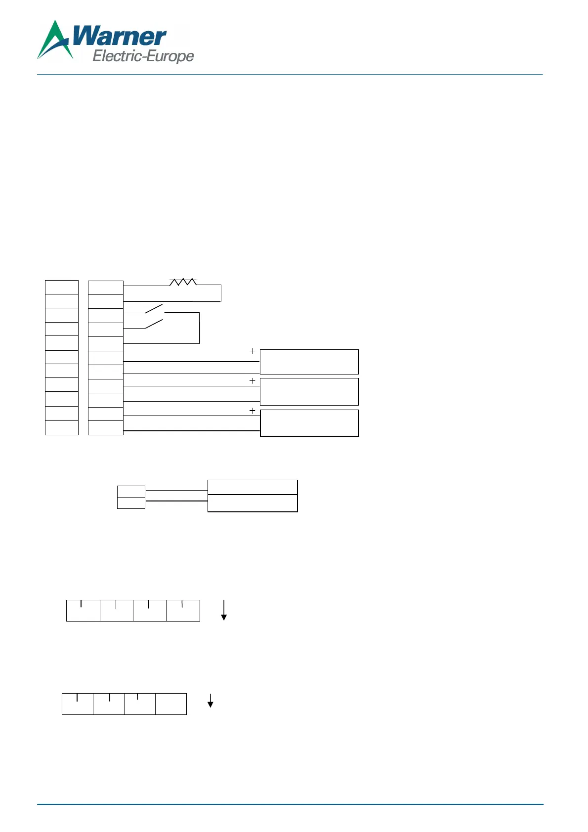
Wiring:
1. Wire 24V DC input power to pin 24V as shown figure 3
24V
GND
2. Connect wiring from brake magnets to Pin BK1 and/or BK2 of the x2DRV as shown figure 2
3. Select the Input type with the red switches located along the bottom of the control:
Off: 4-20mA INPUT
On: 0-10V INPUT (Default)
4. Select the Output type with the red switches located along the bottom of the control:
V/I Off: Output controlled in Voltage: 0-10VDC or 4-20mA IN => 0-24VDC OUT (Default)
V/I On: Output controlled in Current: 0-10VDC or 4-20mA IN => 0-4A OUT
BK1+
BK1-
ON1
OFF1
Gnd
InBK1
Gnd
Ana1
Gnd
10V
Gnd
InBK1
InBK2 An1
An2
V/I
F1
F2
Not
used
Figure 3: Power supply wiring
24VDC can damage the power
supply and/or the driver
Figure 2: x2DRV wiring – one or two brakes
Brake Input signal control
Brake Auxiliary input
External interface Power Supply
C applied to brake, NPN type Input
OFF: Power Off brake 1: 0V applied to brake with anti-residual, NPN type Input
Control or PLC
Potentiometer 1 or 2, others
 Loading...