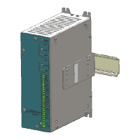
Tension control system X2DRV
29/08/2012
X2DRV Installation & Operation Manual Page 2 of 5
Ratings:
Main Supply Voltage (V)
Compliance
General information:
Control chassis should be kept clear of all areas where foreign material, dust, grease, or all might affect the operation of the control.
Installation must be made in accordance with the instructions found in this manual. Failure to do so may damage the Driver.
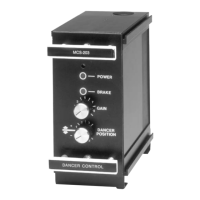
This driver supports the following Warner brakes : TB’s, ATT’s, MPB’s, MPC’s. POB’s, POC’s and MTB’s brakes cannot be driven by this device.
Installation instructions:
Hardware Pin Out:
1 BK1+ Power Output
Integrated Anti-residual control. Voltage or Current controlled.
2 BK1- Power Output
3 BK2+ Power Output
Integrated Anti-residual control. Voltage or Current controlled.
4 BK2- Power Output
5 ON1 Analog input
Active low / GND: NPN type Input
6 OFF1 Analog input
Active low /GND: NPN type Input
8 ON2 Analog input
Full power : 24VDC applied to brake 2
Active low /GND: NPN type Input
9 OFF2 Analog input
Power Off brake 2 : 0V applied to brake 2 with anti
Active low /GND: NPN type Input
11 InBK1 Analog input
Selectable: 0/+10V DC or 4/20mA.
13 Ana1 Analog input
Brake 1 Auxiliary input : T
Brake1 signal in Open Loop control
Selectable: 0/+10V DC or 4/20mA.
Teachable Span (item 9 page 4).
15 10V Power out
Used to Power an external potentiometer to get an Open Loop control (local torque
adjust)
17 InBK2 Analog input
Brake 2 Input signal control.
Selectable: 0/+10V DC or 4/20mA.
19 Ana2 Analog input
Brake 2 Auxiliary input : To compensate Brake2 signal in Open Loop control
Selectable: 0/+10V DC or 4/20mA.
Teachable Span (item 9 page 4).
21 10V Power out
interface Power Supply. 10VDC, 100mA.
Used to Power an external potentiometer to get an Open Loop control (local torque
adjust)
 Loading...