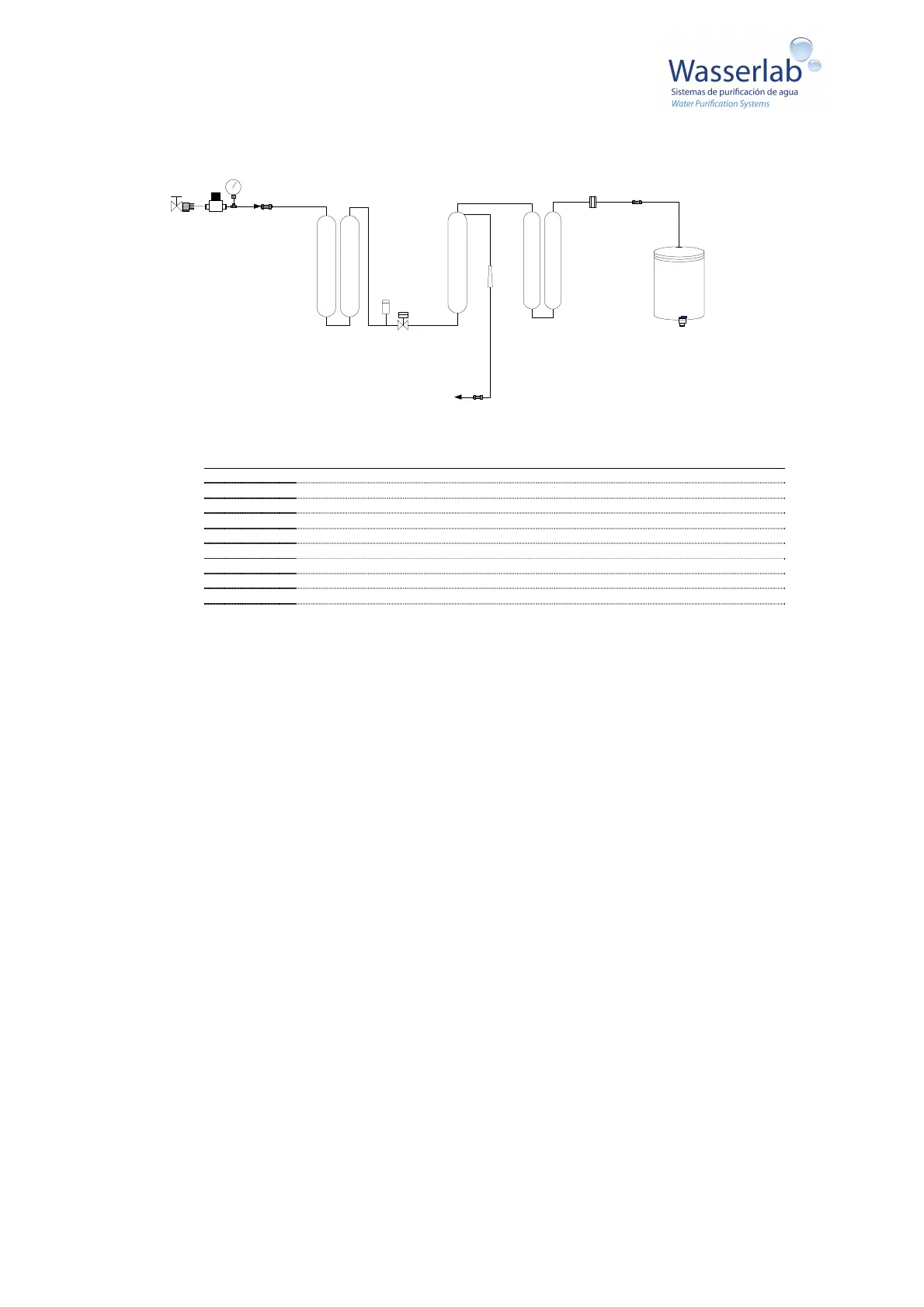
6. Hydraulic diagram
Feed
water
MR MP
[P3]
1
2
PT
PB
EV1
ROM
FR
Rejection
[P1]
3
4
RS
SC3
[P2]
Tank
Type II Water
7. Installation of the equipment
7.1 Unpacking the equipment
- Check that the packaging does not present any kind of damage.
- Carefully unpack the equipment and components. Note if any component is damaged.
- Check that no element of the system is missing:
Micromatic equipment.
Transformer
Spanner wrench
Pipe cutter
1 set of pretreatment cartridges [1] and [2].
1 set of deionization resin cartridges [3] [4]
Tank with level (optional) or Level
User Manual
Water inlet and drainage connection kit.
The equipment is self-supporting. To handle the equipment pick it up from the sides of the base. Note the following
guidelines to locate and connect your equipment:
MR Pressure regulator
MP Pressure gauge
PT Pretreatment 1: Sediment filter, 2: GAC Filter
PB Low Pressure Switch
EV1 Solenoid Valve
ROM Reverse Osmosis Membrane
FR Flow restrictor
TANK Reservoir
RS DI Resin
SC3 Type II conductivity sensor
 Loading...