6
Use Teon tape, Plasto-Joint Stik®† or Silastic RTV #732® on all threaded
connections of plastic pipe and ttings.
DO NOT use pipe compounds on lter; it will cause the
connection to crack. Do not use sealant on unions; assemble
them dry and hand tight.
Support pipe independently to prevent strains on the lter.
Keep piping tight and free of leaks. Pump section line leaks may cause
trapped air in lter tank or loss of prime at pump.
† Lake Chemical Co., Chicago, Ill.
ELECTRICAL:
Be sure that pump grounding meets local and National Electrical Code
Standards. All wiring and grounding of associated equipment must
meet local and National Code Standards.
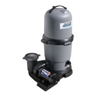
INITIAL START-UP
Be sure pump is OFF before starting procedure.
Do not operate lter at more than 50 PSI (345 kPa).
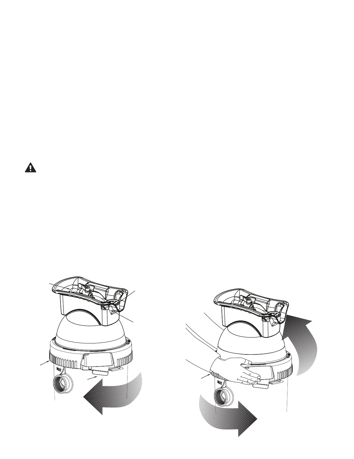
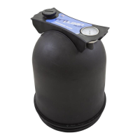
1. Securely lock the Pro-Clean Ring in place by rotating it CLOCKWISE
until it “clicks” past the safety latch (see Figure 3). Stop turning as
soon as the ring clicks past the latch. The ring may feel slightly
loose, but it will tighten up when the pump is on and the lter is
under pressure.
2. Fill the trap on the pump with water.
3. Open the air release valve on top of the lter.
4. Open valves separating the lter from the rest of the system.
5. Start the pump to purge air from the system and stay clear at least 10
feet from the lter.
6. When a steady stream of water comes from the air release valve,
close the valve.
NOTICE: Leaking around the lter ring may indicate that the ring is not
fully locked. In this case proceed as follows:
A. Stop the pump and open the air release valve then release
any pressure within the lter.
B. Remove the drain plug and drain all water from the lter.
C. Rotate the lter ring clockwise until it locks behind the
safety latch (see Figure 3).
D. If the ring was already locked, remove it and the lter lid
assembly. Inspect and clean the O-ring and all sealing surfaces.
Re-lubricate the O-ring, if necessary.
NOTICE: Lubricate the O-ring sealing area inside the upper tank lip with
silicone grease, as other lubricants may cause the O-ring to swell. DO
NOT lubricate the lter ring or the threads on the tank shell as this may
collect grit and make removal dicult.
FILTER DISASSEMBLY /
ASSEMBLY PROCEDURE
BEFORE DISASSEMBLING FILTER:
1. STOP PUMP.
2. OPEN air release valve and drain tting.
3. WAIT until all pressure is released and water drained from
lter tank and system before loosening lter ring.
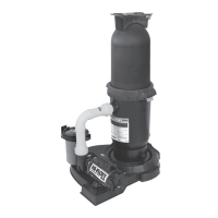
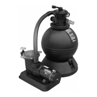
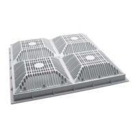
Air Relief
Valve
Pressure
Gauge
Drain
Tube
Filter Ring
Latch
Figure 2
Filter Ring
Figure 3