Do you have a question about the Watson-Marlow qdos120 and is the answer not in the manual?
Explains safety symbols and provides critical warnings for operation and maintenance.
Covers expert consultation, mounting, airflow, temperature, and emergency stops.
Instructions for connecting to an earthed, single-phase mains electricity supply.
Describes the use of M12 connectors for automatic control wiring.
Details pin functions, specifications, and wire colors for pump input connections.
Details pin functions, specifications, and wire colors for pump output connections.
Instructions for safely removing and refitting the relay module cover.
Details cable entry, conductor recommendations, and EMC protection for wiring.
Details the PCB connectors for the 24V relay module, including alarm output.
Explains run status output, remote stop input, and analog speed input for relay modules.
Details the PCB connectors for the 110V relay module, including alarm output.
Explains run status output, remote stop input, and analog I/O for 110V relay modules.
Covers bus connection, adaptors, termination resistors, and bit rate limits.
Details the pin functions and signals for PROFIBUS M12 connector.
Details operation via analog signal and remote stop/reverse inputs.
Explains keypad functions for HOME, START, STOP, and MAX modes.
Describes the manual mode home screen, auto restart, and flow direction indicators.
Guides on enabling PROFIBUS control and setting the station address.
Details how to set the station address from the pump's PROFIBUS settings.
Instructions for enabling/disabling PROFIBUS communication and setting station address.
Explains the PROFIBUS status screen and error indication sequence.
Details setting the fail-safe behavior and speed in case of PROFIBUS communication failure.
Explains the Control Word bits for PROFIBUS data exchange.
Details the Status Word bits for PROFIBUS data exchange.
Guides on selecting flow calibration mode and setting the maximum flow rate.
Procedure to start 4-20mA calibration, choosing manual or analog input.
Allows configuration of Auto keypad lock and PIN protection for security.
Details the padlock icon for keypad lock and PIN protection activation.
Allows setting a lower maximum speed limit for the pump.
Guides on configuring Output 1 and Output 2 status.
Options for configuring the 4-20mA output response: Full scale or Match input scale.
Lists checks for blank display, no flow, and general line issues.
Describes leak detection messages, LED indications, and pumphead replacement.
Lists error codes, their conditions, and suggested actions for internal errors.
Step-by-step guide for removing the Qdos 20, 60, and 120 pumphead.
Reverse procedure for fitting a new Qdos 20, 60, 120 pumphead.
| Brand | Watson-Marlow |
|---|---|
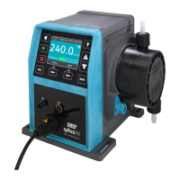
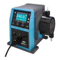
| Model | qdos120 |
| Category | Water Pump |
| Language | English |