EasyManua.ls Logo

Watt Stopper DT-300 User Manual

Watt Stopper DT-300
18 pages
To Next Page IconTo Next Page
Page #1 background imageLoading...
Page #1 background image
U.S. Patent: 7,277,012
Santa Clara, CA 95050
DT-300
v3

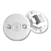
Occupancy Sensor



Voltage .......................... 18-28VDC/VAC, half wave rectified AC
Current Consumption ........................................................25 mA
Power Supply ..................................... WattStopper Power Packs
Isolated Relay Rating ........................................ 1A @30VDC/VAC
Operating Temperature .......................32° to 131°F (0° to 55°C)
Light Level One-Step Adjustment .........................10FC—300FC
Time Delay Adjustment ...................... 30 seconds to 30 minutes
Walk-Through Mode .....3 minutes if no activity after 30 sec
Test Mode ................................ 5 sec. upon DIP switch reset
PIR Coverage (Typical) .....................................................1300 ft
2
Sensitivity Adjustment ....... High or Low (DIP switch setting)
Ultrasonic Coverage (Typical) ..........................................1300 ft
2
Sensitivity Adjustment .........................Min. to Max. (trimpot)
Frequency......................................................................40kHz
UL & CUL Listed for use with WattStopper Power Packs
Question and Answer IconNeed help?

Do you have a question about the Watt Stopper DT-300 and is the answer not in the manual?

Watt Stopper DT-300 Specifications

General IconGeneral
BrandWatt Stopper
ModelDT-300
CategoryAccessories
LanguageEnglish

Summary

COVERAGE PATTERN

PLACEMENT GUIDELINES

WIRING DIRECTIONS

Low Voltage Connections

Details the wiring for RED (+24VDC), BLACK (Return), and BLUE (Control Out) wires.

Manual Switch Wiring

Explains how to connect a manual switch for manual-on functionality.

Isolated Relay Wiring

Describes connections for the isolated relay's common, NO, and NC terminals.

STANDARD WIRING CONFIGURATIONS

MANUAL-ON WIRING CONFIGURATIONS

MOUNTING THE SENSOR

SENSOR ADJUSTMENT

LIGHT LEVEL FEATURE

LIGHT LEVEL SETTINGS MANAGEMENT

DIP SWITCH SETTINGS

Time Delay Configuration

Explains how to set the time delay using DIP switches 1, 2, and 3.

Walk-Through Mode Setting

Details the configuration for walk-through mode using DIP switch 4.

PIR Sensitivity Adjustment

Describes how to adjust PIR sensitivity using DIP switch 5.

Occupancy Logic Options

Covers the 8 logic configurations for occupancy triggers using DIP switches 6, 7, and 8.

MANUAL ON FUNCTION

Manual Mode Operation

Explains how the manual switch functions in Manual Mode (Trigger Options 6 or 7).

Automatic Mode with Manual Switch

Describes additional functionality when using a manual switch in Automatic Mode.

OVERLOAD PROTECTION

TROUBLESHOOTING

No Lights On Entry

Troubleshooting steps for when lights do not turn on upon entering a room.

TROUBLESHOOTING SPECIFIC LED BEHAVIOR

Lights Not Turning Off Automatically

Diagnosing why the lights fail to turn off after occupancy ends.

Lights Fail to Turn Off

Steps to diagnose and fix when lights do not turn off at all.

Related product manuals