Page 2
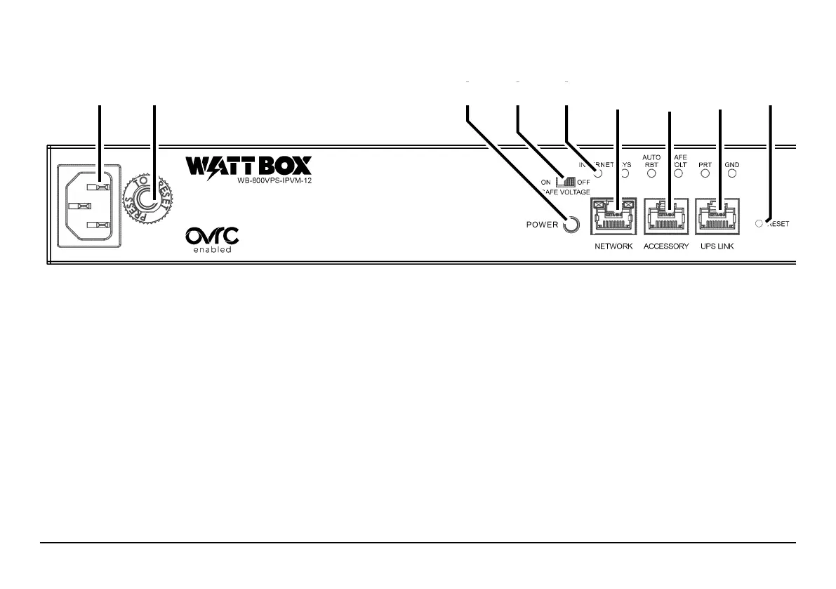
FRONT PANEL
A. Power Inlet: Detachable power cord outlet for 3 prong IEC power cord.
B. Circuit Breaker Reset Button: Press this button to restart the WattBox aer an overload.
C. AC Power switch: Press to manually toggle the outlets on or o. is glows with an amber light when the unit is powered.
D. Safe voltage slider switch: Toggles the “Safe Voltage” feature on and o. On is to the le; o is to the right.
E. Indicator LEDS: See the status of Internet activity, system status, auto reboot, safe voltage, surge protection, and grounding (see
“LED Indicators” on page 9).
F. Network Connection: Connect to the Local Area Nertwork (LAN) for IP control and monitoring.
G. Accessory Port: Not used at this time, but included for future upgrades.
H. UPS Link: For connection to a Wattbox UPS unit.
I. Reset Button: Use a thin tool (paper clip, toothpick) to press this to restart the network card (no settings are changed). Press and
hold 5 seconds to set the power strip to DHCP. Press and hold 10 seconds to reset the power strip to factory default.
A B C D E F G H I
 Loading...