5
sensor
2. Installation
Remove the Thermostat Face
1. Remove the thermostat Front Module
from the Power Module by opening the door
and loosening the screw.
2. 2. Pull outward near the bottom on the
Front Module and lift off. Be careful not
to bend or damage the 14-pin electrical
connector on the back of the Front Module.
Prepare the Wiring
1. Find a location for your thermostat. It is suitable for indoor use only, on
insulated or uninsulated walls. Locate it about 4
1
⁄2 feet to 5 feet above the
oor on an inside wall. Make sure it is well ventilated and not located in a
conned space such as a small closet or cabinet. Avoid placing it near other
heat sources such as hot-water piping, heat duct, wall-mount lighting, and
direct sunlight to help prevent adversely affecting the thermostat.
2. Turn off the power to the oor warming system at the main circuit panel
before doing any electrical work.
3. A qualied electrician should run a dedicated circuit from the main circuit
panel to the thermostat location.
4. If a dedicated circuit is not possible, you may tap from another circuit in the
room. Make sure there is enough load capacity (amps) to handle the addition
of your oor warming system, and that it is NOT wired in series with any other
Owner’s Manual
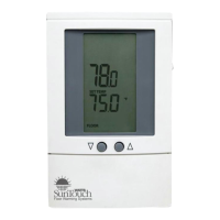
Your new SunStat Pro thermostat is designed to control the voltage to
either a 120VAC or 240VAC resistive oor warming system.
Please follow this manual for complete installation and operation instructions.
If you have any questions or comments, try calling Technical Support at
1-888-432-8932.
CAUTION: Make sure you are qualied and are familiar with house wiring.
This is a line voltage device that could cause serious injury or damage if
improperly installed.
Connect Wires
1. Match and connect the two wires
marked “LINE1” and “LINE2” to the
power supply wires using the wire nuts
provided.
2. Gently tug on the wires to make sure
they are secure, otherwise a wire could
loosen and cause failure.
3. Overwrap the wire nuts with electrical
tape to better secure them to the wires.
4. Match and connect the two wires
marked “LOAD1” and “LOAD2” to the
oor warming system lead wires and
secure these wires the same way.
5. Connect the house ground wire to the
green or bare lead wire(s) of your oor
warming system.
6. Insert the ends of the oor sensor
wire into the “SENSOR” terminals (1 and
2) and tighten the screws. There is no
polarity, so it does not matter which wire
end goes into which terminal.
CAUTION: Before continuing, make
sure your power supply voltage matches
the voltage rating of your oor warming
system.
Connecting 240V to a 120V oor warm-
ing system will cause overheating and
damage to the system and may damage
the control, other wiring, oor coverings,
etc.
Remote Control
1. If you want to connect your thermostat to a remote control device, such as
a home automation system, rst make sure that the remote device has a “dry
contact, normally open” output (an un-energized switch, such as the contacts on
a relay). Many home automation systems come with such an output that opens
or closes at specied times.
2. Pull 2-conductor wire, size 18- to 24-guage, through the wall from the remote
device, into this electrical box.
3. Connect the wire ends into the “SETBACK” terminals (5 and 6) and tighten
the screws (no polarity).
SunStat Relays
1. If you want to use your thermostat to drive a SunStat Relay(s) (ask your dealer
about this convenient way to control larger systems with one thermostat), rst
read and follow the instructions for the SunStat Relay thoroughly.
2. Pull 2-conductor wire, size 18- to 24-gauge, through the wall from the SunStat
Relay, into this electrical box. This wire may be up to 100 feet (30 m) in length
from the thermostat to the last SunStat Relay installed.
3. Connect the wire ends into the “RELOUT” terminals (3 and 4) and tighten the
screws(Observe polarity of the wires when connecting to the SunStat Relay).
Mount the Thermostat
1. Carefully fold and press the wires back into the electrical box. Do not use
the thermostat to push them in, as this may cause connections to loosen and
possible failure.
2. Secure the thermostat Power Module into the box with the mounting screws
provided.
3. Carefully align the Front Module with the
Power Module to avoid bending any of the
pins on the Front Module while snapping
them together.
4. Tighten the screw.
5. Switch on the power at the main circuit
panel.
NOTE to contractors: After installing the
thermostat, be sure to:
a. Do a Quick Setup (section 3),
b. Temporarily override the setpoint
SunStat Pro
Programmable Thermostat
Model 500670
1-4
from
power
supply
to
oor
warming
system
1. Preparation
1. Unpack your thermostat and make sure everything is in good condition:
•Thermostat
•Floor sensor
•Small screwdriver
•Mounting screws
•Wire nuts for wiring connections
If any parts are missing or damaged, contact the store where you purchased
this thermostat. Do not install a damaged part.
2. Gather the following tools and supplies:
•Phillips screwdriver, hole saw
•Wire strippers, “sh tape”, other electrical tools
•Electrical box for thermostat:
a. If you are connecting to power leads from only 1 or 2 oor warming
systems, you may use a single-gang, 3
1
⁄2 inch deep box.
b. If you are connecting to power leads from 3 oor warming systems,
use a 4x4x2
1
⁄8 inch or deeper box (not a 2-gang box) when your wall studs
are still exposed. Install a single-gang “mud-ring” cover on the box before
installing drywall materials.
c. For more than 3 oor warming systems or other layouts, you may need
to install a junction box to connect the power leads together. Then use
house wire to connect between the junction box and the thermostat
electrical box. See the installation instructions for your oor warming
system for more information.
ALWAYS: Wire all circuits as Class 1, Electric Light and Power Circuits.
ALWAYS: Wire all circuits with insulation rated 600V minimum.
ALWAYS: Mount this control only to a grounded metallic box or a
nonmetallic box.
ALWAYS: Use power supply wires suitable for at least 90°C.
CAUTION: High voltage – disconnect power supply before servicing.
CAUTION: The GFCI in this control does not protect against shock if both
bare conductors are touched at the same time.
device, including other GFCIs.
5. The circuit breaker in the main circuit panel should be 15 amps maximum
for a oor warming system totaling 12 amps or less. For larger systems up
to 15 amps, use a 20 amp maximum circuit breaker. Never exceed 15 amps
on this thermostat. You may consider using an arc-fault (AFCI) type circuit
breaker for additional protection.
6. Mount the electrical box.
7. Pull the power supply wiring into this box, leaving about 6 inches of wire.
8. Pull the oor sensor wire and the power lead wires from your oor warming
system up the wall, into this box. Refer to your oor warming system
installation instructions for placement of the oor sensor tip into the oor area.
Note: The sensor wires should not be run in the same conduit as line voltage
wires to avoid possible interference. If the sensor lead wires are not long
enough, they may be extended an additional 15 feet (4.5 m) using minimum
20-gauge 2-conductor wire or up to 50 feet (15 m) using shielded wire.
power
module
front
module