3.2
OPERATION
Operation
is
described
as
function generator operation and.
synthesizer operation. The generator
is
ready
to
operate as
soon as a frequency multiplier
is
selected.
3.2.1
Signal
Termination
Proper signal termination,
or
loading,
of
the
generator con-
nectors
is
necessary for its specified operation.
For
example,
the proper termination
of
the
500
OUT
connector
is
shown
in
figure 3-3. Placing
the
50
ohm
terminator,
or
50
ohm
re-
sistance, in
parallel
with a higher impedance, matches
the
receiving instrument
input
impedance
to
the
generator out-
put
impedance, thereby
mii:iimizing signal reflection
or
power
loss on
the
line due
to
imp.edance mismatch.
MODEL
171
OUTPUT
IMPEDANCE
son
RGS8 OR
RECEIVING
INSTRUMENT
EFFECTIVE
EQUIVALENT
CIRCUIT
son
RESISTANCE
Figure 3-3.
Signal
Termination
The
input
and
output
impedances
of
the generator
connec-
tors are listed below:
Connector
Impedance
50n
OUT
50n
600n
OUT
600n
TTL
OUT
*
REF
OUT
VCGIN
2kn
GCV
OUT
600Q
REFIN
5kQ
*The TTL
OUT
connector
can drive up
to
20
Transistor-
Transistor Logic (TTL) loads {low
level
between
OV
and
0.4V, and high
level
between 2.4V and 5V). REF
OUT
can
drive up
to
3 TTL loads. Addition
of
the TTL buffer option
gives
these
outputs
the capability of driving a
50Q
load.
3.2.2
Manual Function Generator
Operation
For basic operation, select the waveform frequency and
amplitude. The
following
steps demonstrate
manual
control
of the function generator.
(Circled
numbers are keys
to
figure 3-1.)
Step
2
3
Control/Connector
50UOUTor
600nOUT
Dial/Digital
Switch
Selector
@
FREQ
MULT
Setting
Connect
circuit
to
either
output
(refer
to
para-
graph 3.2.1
).
Set
toward
the
dial.
Set
to
desired range
of
fre-
quency.
4
Frequency Dial
G)
.Set
to
desired frequency
within
the
range.
5
Waveform Selector
@
Set
to
desired waveform.
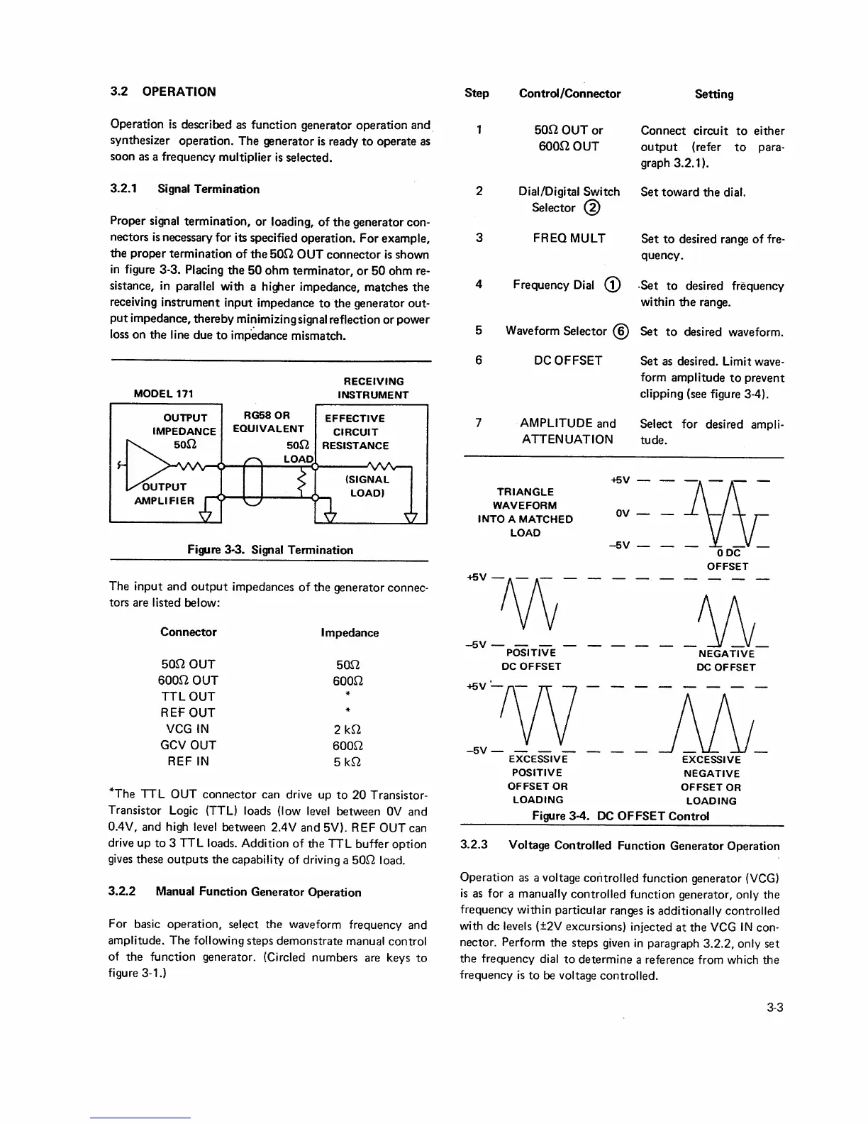
6
7
DC
OFFSET
AMPLITUDE
and
ATTENUATION
Set
as desired. Limit
wave-
form amplitude
to
prevent
clipping (see figure 3-4).
Select
for desired
ampli-
tude.
+5V -
~
TRIANGLE
WAVEFORM
INTO
A
MATCHED
LOAD
<fiV-1\fv-
-5V-
- - -
POSITIVE
DC
OFFSET
<fiV~w
-5V-
- - -
EXCESSIVE
POSITIVE
OFFSET OR
ov
-
-5V
-
-
ODC
-
OFFSET
_Aj1_
NEGATIVE
DC
OFFSET
M_
EXCESSIVE
NEGATIVE
OFFSET
OR
LOADING
LOADING
Figure 3-4.
DC
OFFSET
Control
3.2.3
Voltage Controlled
Function Generator Operation
Operation
as
a voltage
controlled
function generator
(VCG)
is
as for a
manually controlled function generator, only
the
frequency within particular ranges
is
additionally
controlled
with
de
levels (±2V excursions} injected
at
the
VCG
IN
con-
nector. Perform the steps given
in
paragraph 3.2.2, only set
the frequency dial
to
determine a reference from which the
frequency
is
to
be
voltage controlled.
3-3
 Loading...