1.
2.
3.
For
frequency
control
with
positive
de
inputs
at
VCG
IN,
set
the
dial for a lower frequency limit.
For
frequency
control
with
negative de inputs
at
VCG
IN,
set
the
dial for an
upper
frequency limit.
For
modulation
with
an ac
input
at
VCG
IN,
set
the
dial
at
the
desired
center
frequency. Do
not
exceed
the
maximum
dynamic
range
of
the
selected frequency
range.
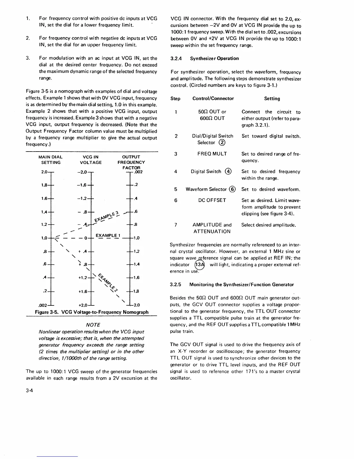
Figure
3-5
is
a nomograph
with
examples
of
dial and voltage
effects. Example 1 shows
that
with
OV
VCG
input,
frequency
is
as
determined
by the main dial setting,
1.0
in
this example.
Example 2 shows
that
with
a positive VCG input,
output
frequency
is
increased. Example 3 shows
that
with a negative
VCG
input,
output
frequency
is
decreased. (Note
that
the
Output
Frequency
Factor
column
value
must
be multiplied
by a frequency range multiplier
to
give
the
actual
output
frequency.)
MAIN
DIAL
SETTING
2.0
1.8
1.6
1.4
1.2
1.0
-
"'
'
.8
.6
.4
.2
-
-
'
'
VCGIN
VOLTAGE
OUTPUT
FREQUENCY
FACTOR
.002
-2.0
-1.6
. 2
-1.2
.4
.6
-
.8
""~\..~;..
~"/..~
-
-
.4_..
.8
-0
EXAMPLE
1
- -
-
1.0
+
.4
1.2
'
+ .8
1.4
'
1.8
+1.2
'~+
,~~
,:oo<
+1.6
~..?
1.6
'
'
.002 +2.0 2.0
Figure 3-5. VCG Voltage-to-Frequency Nomograph
NOTE
Nonlinear operation results when the
VCG
input
voltage
is
excessive; that
is,
when the attempted
generator frequency exceeds the
range
setting
(2
times the multiplier setting) or in the other
direction, 1 /1000th
of
the range setting.
The
up
to
1000:
1 VCG sweep
of
the
generator frequencies
available
in
each range results from a 2V excursion
at
the
3.4
VCG
IN
connector. With
the
frequency dial
set
to
2.0, ex-
cursions between
-2V
and
OV
at
VCG
IN
provide
the
up
to
1000: 1 frequency sweep. With
the
dial
set
to
.002,
excursions
between
OV
and +2V
at
VCG
IN
provide
the
up
to
1000: 1
sweep within the
set
frequency range.
3.2.4
Synthesizer
Operation
For
synthesizer
operation,
select
the
waveform, frequency
and amplitude. The following steps
demonstrate
synthesizer
control. (Circled numbers are keys
to
figure 3-1.)
Step
2
3
4
5
6
7
Control/Connector
50f2 OUT
or
6000
OUT
Dial/Digital Switch
Selector
@
FREQ
MULT
Digital Switch
@
Waveform
Selector@
DC
OFFSET
AMPLITUDE
and
ATTENUATION
Setting
Connect
the
circuit
to
either
output
(refer
to
para-
graph 3.2.1
).
Set
toward
digital switch.
Set
to
desired range
of
fre-
quency.
Set
to
desired frequency
within
the
range .
Set
to
desired waveform.
Set
as
desired. Limit wave-
form amplitude
to
prevent
clipping (see figure 3-4).
Select desired amplitude.
Synthesizer frequencies are normally referenced
to
an inter-
nal crystal oscillator. However, an external 1 MHz sine or
square
wav~erence
signal can be applied
at
REF IN;
the
indicat~r
e will light, indicating a
proper
external ref-
erence
in
use.
3.2.5
Monitoring
the
Synthesizer/Function
Generator
Besides the 50f2 OUT and 600f2 OUT main generator out-
puts, the GCV OUT
connector
supplies a voltage propor-
tional
to
the generator frequency, the
TTL
OUT
connector
supplies a TTL
compatible
pulse train
at
the
generator fre-
quency, and the REF
OUTsuppliesaTTLcompatible
lMHz
pulse train.
The
GCV OUT signal
is
used
to
drive
the
frequency axis
of
an
X-Y
recorder or oscilloscope; the generator frequency
TTL OUT signal
is
used
to
synchronize
other
devices
to
the
generator
or
to
drive
TTL
level inputs, and
the
REF OUT
signal
is
used
to
reference
other
171 's
to
a master crystal
oscillator.
 Loading...