5
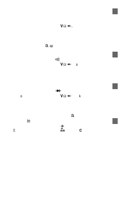
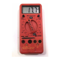
Measuring Resistance See Figure -5-
1. Set the Function Switch to Ω.
2. Select the desired RANGE (5XP only).
3. Connect the test leads: Red to
E
, Black to COM.
4. Turn off power to the circuit being measured. Never measure resistance across
a voltage source or on a powered circuit.
5. Discharge any capacitors that may influence the reading.
6. Connect the test probes across the resistance.
7. Read the display. If
0o
appears on the highest range, the resistance is too large
to be measured or the circuit is an open circuit.
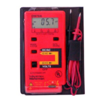
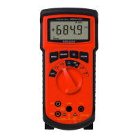
Testing for Continuity See Figure -6-
1. Set the Function Switch to
R
.
2. Connect the test leads: Red to
E
, Black to COM.
3. Turn off power to the circuit being measured.
4. Discharge any capacitors that may influence the reading.
5. Connect the test probes across the resistance.
6. Listen for the tone that indicates continuity (< 40 Ω).
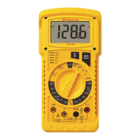
Testing Diodes See Figure -7-
1. Set the Function Switch to
G
.
2. Connect the test leads: Red to
E
, Black to COM.
3. Turn off power to the circuit being measured.
4. Free at least one end of the diode from the circuit.
5. Connect the test probes across the diode.
6. Read the display. A good diode has a forward voltage drop of about 0.6 V. An
open or reverse biased diode will read
0o
.
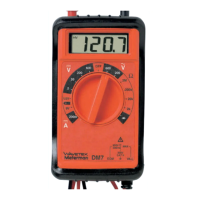
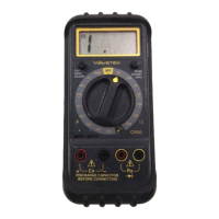
Measuring Capacitance (35XP only) See Figure -8-
1. Set the Function Switch to the
P
function.
2. Connect the test leads: Red to
h
,
Black to COM.
4. Turn off power to the circuit being measured.
5. Discharge the capacitor using a 100 kΩ resistor.
6. Free at least one end of the capacitor from the circuit.
7. Connect the test probes across the capacitor.
8. Read the display.