CHAPTER 12 CLICK 172/174 135
Low Power (LP)
Note
The first number in the lane name is the number specified in SmartSensor Manager.
If no number is specified, this space will remain blank. The second character is “L” or
“r” (Left or Right) and indicates the direction of travel from the perspective of stand-
ing behind the sensor.
e devices feature LEDs that turn on to indicate vehicle detection. Depending on the op-
erating mode, the LED will remain on for dierent durations.
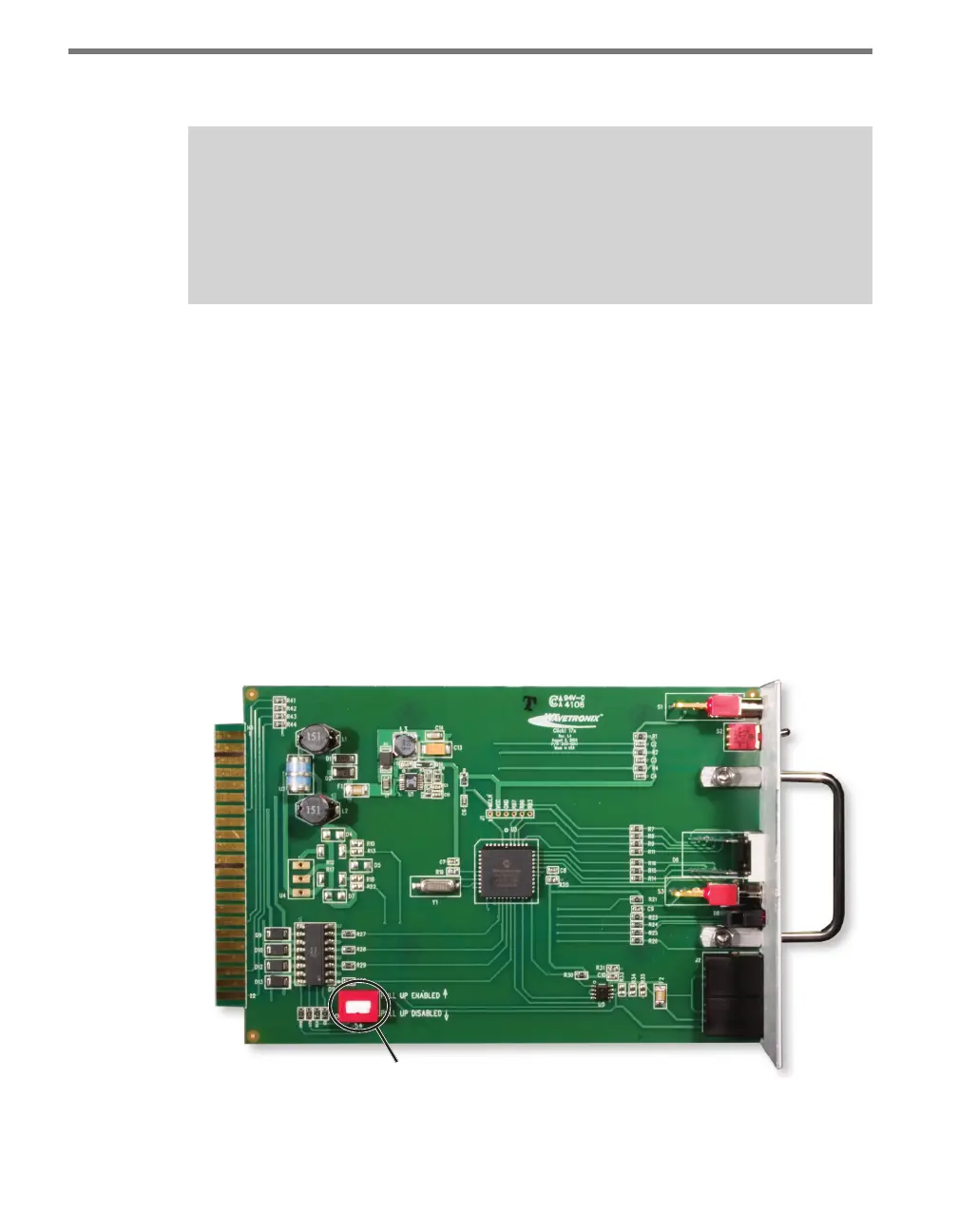
e Click 172/174 may also have a DIP switch, located on the bottom-le corner of the
Click 172/174 circuit board, which enables voltage output (as opposed to contact closure
output). By default, the DIP switch is down (disabled) because most standard controllers
(and bus interface units) require a contact closure output.
Do NOT put the DIP switch in the up (enabled) position unless you have a special appli-
cation that requires a voltage output instead of a contact output. If the switch is enabled,
the rack card will pull its backplane contact pins high (to 12 or 24 VDC, depending on the
card’s operating voltage) when the output is open. is provides a voltage output instead of
a contact closure output. In either case, when a detection call is active, the associated rack
card output will close (see Figure 12.3).
DIP Switch
Figure 12.3 – DIP Switch
Once the contact closure card is congured, the controller’s detector inputs must be set up