CHAPTER 12 CLICK 172/174 137
1L (One Loop Speed)
Outputs contact closures for single-loop emulation. The duration of
each contact closure output is based upon the speed of the detected
vehicle (instead of the duration of the vehicle in the beam). The
duration of each contact output is based on the formula: duration in
seconds = nominal vehicle length in feet / actual speed in feet per
second. The nominal vehicle length is read from the sensor when this
mode is selected. To set the nominal vehicle length, use the Smart-
Sensor Manager software. The nominal length in feet is entered in
the default loop spacing field.
Table 12.1 – Click 172/174 Operation Modes
A dual-loop emulation system uses two rack card channel outputs to mimic the outputs
of a traditional dual-loop system. In a traditional system, a vehicle would travel over the
primary detector and then the secondary detector (see Figure 12.4).
Figure 12.4 – Primary Leads Secondary
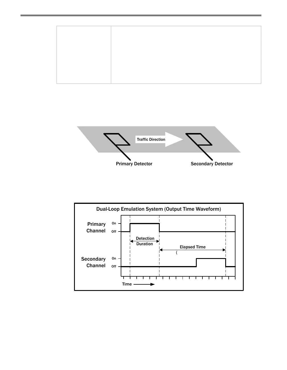
Figure 12.5 below shows a diagram of the output signal time waveforms of the two detec-
tors.
Dual-Loop Emulation System (Output Time Waveform)
Indicates Speed)
Figure 12.5 – Emulation System Output Waveforms
e primary detector channel output would activate for the duration that the vehicle was
over the primary loop. Soon aerward, the secondary detector channel output would acti-
vate for the duration that the vehicle was over the secondary loop. e elapsed time between
the two activations indicates the speed of the vehicle. (e duration of the detection is based
upon the speed and length of the vehicle.)