96 CHAPTER 9 CLICK 110
Note
This parameter can also be changed using the DIP switches or Click Supervisor.
As mentioned earlier, the Click 110 device receives serial datagrams from a SmartSensor.
ese datagrams can contain many channels of detection data. Because the Click 110 has
four output channels, only four input datagram channels, received from the sensor, can
be output by each device. (If you need more than four channels, consider using multiple
devices.) As shown in the table below, the outputs are mapped sequentially—that is, they
can only be mapped in numerically ordered groups of four (1–4, 5–8, etc.). If you chose, for
example, 17–20, then input 17 would be mapped to output 1, input 18 would be mapped to
output 2, input 19 would be mapped to output 3, and input 20 would be mapped to output 4.
If fewer than four outputs are required, any contact closure output can be disabled (covered
later in this section). A disabled output will never enter the detection state, and will never
indicate a fault condition. Depending on whether each channel is enabled or disabled, the
input mapped to it will also be enabled or disabled.
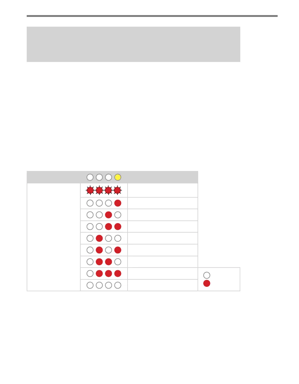
Level 1 LEDs
Input Mapping
Level 2 LEDs
Channels 1–4
Channels 5–8
Channels 9–12
Channels 13–16
Channels 17–20
Channels 21–24
Channels 25–28
Channels 29–32
LED o
LED on
Cancel and exit menu
Table 9.8 – Front Panel Menu Channel Input Map Settings
See the earlier Navigating through the Menu and the Menu Operation Example sections for
how to congure this parameter.
Because this parameter can also be set by the DIP switches, you may need to ensure that the
DIP switches are set to Soware conguration mode; if they are set to Hardware, the front
panel menu will be able to display but not change these settings.