CHAPTER 9 CLICK 110 95
Level 1
LEDs
Autobaud Settings
Perform Autobaud on Bus 1
Perform Autobaud on Bus 2
Cancel and Exit Menu
Level 2
LEDs
Level 1
LEDs
Fault Latch
Fault Latch Enabled (default)
Fault Latch Disabled
Level 2
LEDs
Level 1
LEDs
Outstation Support Settings
Peek Outstation Support (default)
Siemens Outstation Support
Level 2
LEDs
Level 1
LEDs
Reset to Default Settings
Cancel and Exit Menu
Reset to Default Settings
Level 2
LEDs
Baud Rate Setting for Bus 1
LEDs
Baud Rate = 9600 (default)
Baud Rate = 57600
Baud Rate = 19200
Baud Rate = 115200
Baud Rate = 38400
Cancel and Exit Menu
Level 2
LEDs
Baud Rate Setting for Bus 2
Level 1
LEDs
Baud Rate = 9600 (default)
Baud Rate = 57600
Baud Rate = 19200
Baud Rate = 115200
Baud Rate = 38400
Cancel and Exit Menu
Level 2
LEDs
Channel Enable
Level 1
LEDs
All Channels Disabled
(default)
Enable Channel 3
Enable Channel 1
Enable Channel 4
Enable Channel 2
Channel: 1 2 3 4
Cancel and Exit Menu
Level 2
LEDs
Level 1
LEDs
Channel Input Map
Channels 25 - 28
Channels 29 - 32
Cancel and Exit Menu
Channels 21 - 24
Channels 17 - 20
Channels 13 - 16
Channels 1 - 4
Channels 5 - 8
Channels 9 - 12
Level 1
LEDs
Channel Input Map
Reset to Default Settings
Cancel and Exit Menu
Outstation Support Settings
Fault Latch
Channel Enable
Autobaud Settings
Baud Rate Setting for Bus 1
Baud Rate Setting for Bus 2
• Press and hold Mode Switch to cycle through options
• Press and release Mode Switch to select option
NOTE: If a settings DIP switch is not set to SW Cong,
then the current setting is displayed but cannot be
modied using the Mode Switch.
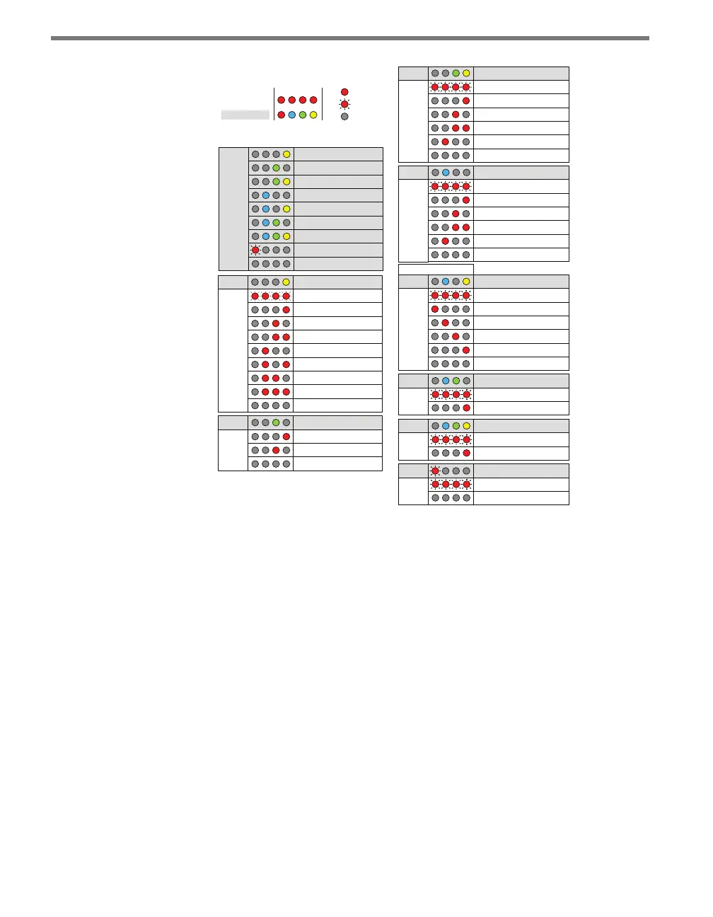
On
Blinking
Off
Level 1 LEDs
Level 2 LEDs
Menu
1 2 3 4
Using the Mode Switch to
View or Modify Conguration
Figure 9.8 – Front Panel Menu Label
As shown above, the menu options are displayed on the Level 1 LEDs and the conguration
parameters are displayed on the Level 2 LEDs.
If a conguration parameter has been set using the DIP switches (meaning that parameter
is currently set to Hardware mode), you cannot change it using the front panel menu. Aer
selecting that particular menu option from the Level 1 LEDs, the Level 2 LEDs will display
the conguration option set in the DIP switches and will not allow you to switch from that
option. e only way to exit at this point is to press the push-button once.
Channel Input Map
e rst conguration parameter that comes up when you’re cycling through the front
panel menu is the channel input map. To select this parameter, release the push-button
when the yellow LED comes on solid.