4
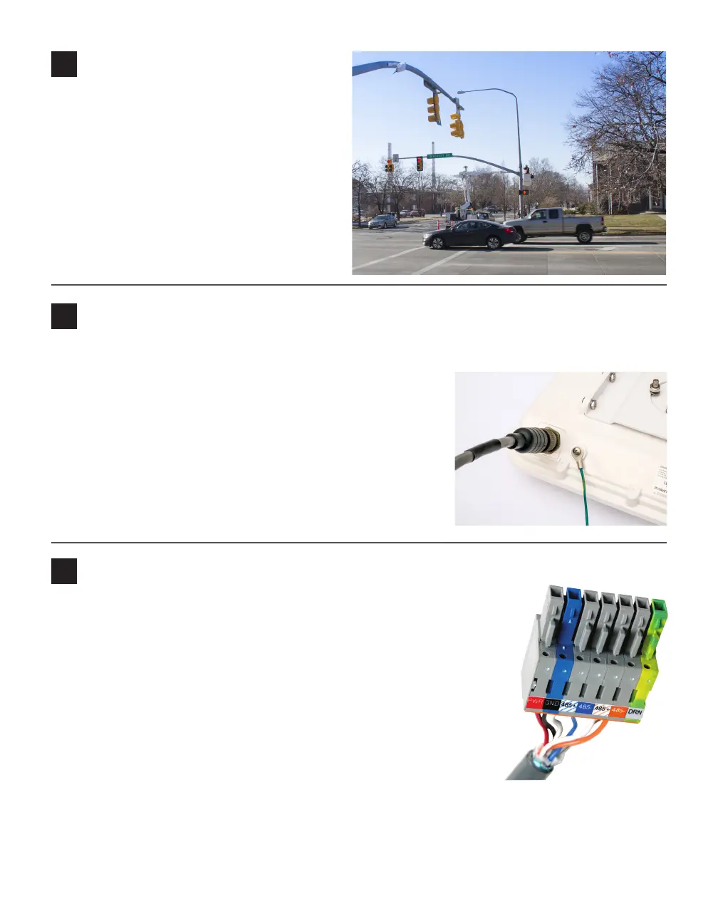
Align the sensor to the roadway
1 Adjust the side-to-side angle so the front edge
of the radar’s footprint covers the entire stop
bar and beyond so you can detect vehicles
that don’t stop at or behind the line, as well as
vehicles exiting queues.
2 Tilt the sensor down to aim it at the center of
the lanes of interest.
3 If the intersection approach has a signicant
grade, rotate the sensor so the bottom edge is
parallel with the roadway.
5
Attach the 6-conductor cable and ground the sensor
1 Squeeze 25% of the silicon dielectric compound into the connector at the base of the sensor; wipe o excess.
2 Insert the cable into the connector and twist clockwise until you
hear it click into place.
3 To avoid undue movement from wind, strap the cable to the pole
or run it through a conduit with enough slack to reduce strain.
4 Connect a grounding wire to the grounding lug on the bottom of
the sensor.
5 Connect the other end of the grounding wire to the earth ground
for the pole that the sensor is mounted on.
6 Route the service end of the cable back to the main trac cabinet.
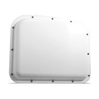
6
Terminate cables
Terminate the sensor cable into one of the four ports on the back of the Click
650. For each sensor you want to connect to the Click 650, do the following:
1 Remove one of the plugs from the back (they are numbered 1–4; you’ll
need to keep track of which sensor is plugged into which port).
2 Terminate the conductors from the cable into that plug, following the
labels on the plug (as shown at right), then reconnect the plug to the
Click 650.
3 Each sensor port has a corresponding RJ-11 jack, LED, and switch on
the faceplate of the Click 650. Make sure the switch is turned on.
4 On the faceplate of the device is an SDLC port; connect a cable there to
connect the Click 650, and its attached sensors, to the SDLC bus and, via
that bus, to the controller.
NOTE. If your cabinet doesn’t support SDLC, you can connect from the sensor port RJ-11 jacks to contact
closure cards and communicate with the controller that way.