25
Wavin AS+ Technical Manual
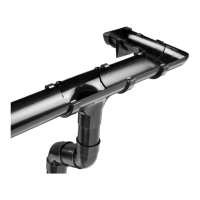
Collecting connection pipes
Collecting connection pipes collect waste water from various single connection pipes and carry it to the next pipe section
(e.g. a downpipe). Here, too, the load-bearing limitations apply. Ventilated collecting connection pipes therefore deliver
considerably better performance than unventilated ones.
The layout dimensions of collecting connection pipes are established by adding together the discharge units (DU) of the corres-
ponding section of collecting connection pipe (∑DU), using tables 5+6, subject to the corresponding freqency factor K.
The following also applies:
Minimum fall J= 1cm/m.
The sum total of discharge units must not exceed ∑DU = 16.
The limitations for unventilated/ventilated collecting connection pipes must be observed.
A distinction must likewise be made between unventilated and ventilated collecting connection pipes when carrying out
dimensional calculations.
Dimensional calculations are based on the Prandtl-Colebrook formula.
Application boundaries for unventilated collecting connection pipes
Nominal diameter Di Max. length Max. number of Max.height Minimum fall
DN mm of pipe m changes of difference %
direction (90°) M
50 44 4.0 3 1.0 1
56 49 4.0 3 1.0 1
70 68 4.0 3 1.0 1
80 75 10.0 3 1.0 1
90 79 10.0 3 1.0 1
100 96 10.0 3 1.0 1
Application boundaries for ventilated collecting connection pipes
Max. length of pipe Max. number of changes of direction (90°) Max. height difference Minimum fall
m M %
10.0 No limit 3.0 0.5
Table 7: Application boundaries for unventilated collecting connection pipes conforming to DIN 1986-100.
Table 8: Application boundaries for ventilated collecting connection pipes conforming to DIN EN 12056-2, Table 8.