b Verify the fuse is a constant fuse by a multimeter.
Pull
out
the
identified
constant fuse from the fuse
panel.
Use
the fuse
puller
tool
if
available.
c.
Remove the
sleeve
from the end
of
the
yellow
BATT+ wire, and
wrap
the
wire
around one
of
the
blades
of
the Constant Power fuse.
d.
Reinsert the fuse back into the fuse
panel.
5.
Connect the black
GND wire
to
a ground point, such
as
a
bolt,
that
is directly
on a bare
metal
pa
rt
of
the
vehicle's frame.
6.
Verify the Direct Wire connections:
a.
Power on the Secure360
by
following
step 2
"Connect
power
to
the
Secure360 Dock"
on page
8.
The camera should then behave
as
follows:
i.The Status
LED
will
turn
on
immediately
after
the
connection
of
USB
Type-C
plug.
ii. One
minute
later
the status
LED
will
turn
off
as
long
as
the sensors
do
not
detect sound and movement.
iii. The Status
LED
will illuminate white
if
the
vehicle accessory
power
is turned
on
or
if
the engine is started.
It
will
turn red then
while
a
SO
card is inserted.
1v.
The Status
LED
will discontinue one
minute
after
turning
off
the accessory
power
or
the engine.
b. Check the
wire/fuse
connections
if
the
camera does
not
work
as expected.
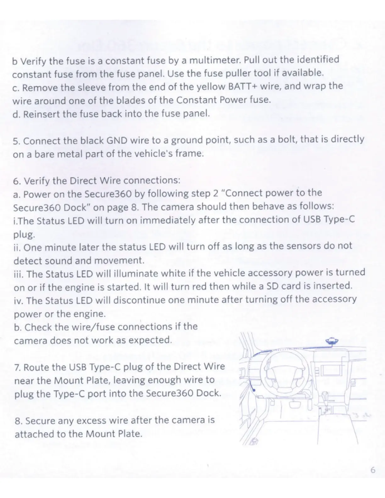
7.
Route the
USB
Type-C
plug
of
the Direct
Wire
near the
Mount
Plate, leaving enough wire
to
plug the Type-C
port
into the Secure360 Dock.
8.
Secure any excess wire
after
the camera is
attached
to
the
Mount
Plate.
f
6
 Loading...